Transistor amplifier
In general, a transistor amplifier is a circuit for amplifying an analog signal or a digital data carrier signal.
For example, the output audio signal of a microphone is very weak and the audio oscillation is in a very low voltage range. With a transistor audio amplifier, its output can be increased to the standard input range of a speaker.
Suppose the audio signal output of a microphone is at 0.005 watts range, then by using a transistor amplifier with an amplification factor of 1000, you can connect the output of the microphone to a 5-watt speaker.
Transistor amplifier for audio signal
The following circuit is an audio amplifier with two stages of the amplification and a capacitive microphone:
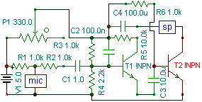
Circuit analysis:
In this circuit, the current reaches to the input of the microphone after passing through the resistor R1, and the microphone also creates a kind of variable resistance by changing the frequency and amplitude of the environment audio.
The higher the frequency of the input audio, causes more resistance changes, and loud sound causes higher and lower resistance according to the DC level in this type of microphones.
With a little investigation, you can find out that:
1- The louder the sound, causes the less current drain between R1 and R2, so the rms voltage between R2 and C1 will be higher.
2- The quieter the sound, causes the less current reaches to the C1 capacitor.
The current that passes through the capacitor enters to the transistor.
In order not to have problems with amplifying the negative waves, we must add a little initial voltage (DC Level) and current to the base pin of the T1 (because of the construction of the transistors) with help of R3 and R4. The value of the resistor can be easily calculated.
C2 is placed to filter the DC level noises.
The output of the T1 transistor (the first stage of the amplifier), enters to the C3 capacitor from its emitter to remove the DC level from the amplified audio signal.
R6 Resistor also provides the DC level for the second stage of amplification.
After passing through the first and second stage, the current causes the enough amplification at the collector of T2.
The signal that enters to the speaker through this circuit, causes to producing the sound.
- From the output of the speaker (T2 collector), connect a reverse bias diode to the negative of the power source (GND) to avoid the voltages below zero volt, or feed the collector with the maximum current.
- The diode you connect must be toward to the signal, (reverse bias/suppose the current input is from GND to the speaker).

Written by: M. Mahdi K. Kanan – Full stack electronics and programming engineer and the founder of WiCardTech