Capacitor and how to use it in the circuit
In most of the books about the use of capacitors, it is written in such a way that the capacitor stores electric charge in itself and discharges it when necessary. What we need to know is when should the capacitors be charged and when should they be discharged and how is this possible?
Therefore, first of all, we must know the action that capacitors perform by connecting the current:
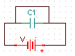
Suppose we are going to connect a capacitor to a power supply with a load resistor as the current limiter.
Before connecting the power supply, the capacitor voltage (between its pins) and current are zero.
At the beginning of connecting the two pins of the capacitor, the voltage is zero, and the current in at its maximum rate. In the other word, the capacitor acts like a wire.
After the passage of each step/level (τ), the voltage of the capacitor increases to 63.7 percent of its previous value and it doesn’t let pass 63.7 percent of the current.
After 5 steps (5τ), the capacitor is almost fully charged, and the capacitor won’t let the current passing through.
After this, it can be concluded that capacitors act like a switch in front of direct current, which does not pass current after some time.
This time can be even less than 0.001 seconds, depending on the capacity of the capacitors and the amount of passing current.
Types of capacitors and their capacity
There are different types of capacitor such as: lens capacitor, electrolytic capacitor, ceramic capacitor, mica capacitor, etc.
The capacity unit is Farad (F) and the capacitors denoted by C in the schematic plans.
Lens capacitors are usually used for lower capacity.
Electrolytic capacitors are used for high capacities, because they are cylindrical and have more parallel plates.
lens capacitor:


Electrolytic capacitor (polarized):


When using polarized capacitors, its positive pole must be connected to the higher voltage (current input) and its negative pole to the lower voltage (current output/e.g. ground). In these capacitors, the negative pin (shorter leg) is marked on the body with the sign “-” above the pin.
- In the circuits which space is limited, such as boards inside a computer and mobile devices, SMD capacitors, diodes, resistors and transistors are used.
- The capacity of SMD parts is written on the part. In such a way that the last digit shows the number of zeros in front of the first digits and its unit is also the smallest possible unit; For example, in a capacitor, it is 1 pico-farad (pF).
To calculate capacity, we need the voltage and load.
To get the load, special formulas should be used.
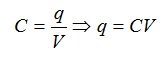
Usually, we have the capacity and voltage, and we get the charge stored in the capacitor through the following formula
The standard of the capacitors’ available capacity values in the markets is the same as resistors E12 and E24 standards.
Calculation of the energy stored in the capacitor
It may not be very useful to calculate the energy stored in capacitors, but other values can be obtained by using its relationships.
Electric energy is denoted by U and its unit is Joule (j) and it is calculated with the following relations:
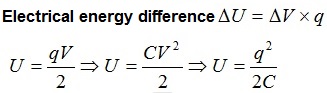
In the above relationships, Δ means difference, the electric energy difference is ΔU and ΔV is the voltage or electrical potential difference between the pins or between the moments (V2-V1).
Connecting the capacitors together
Like resistors, capacitors can be connected to each other in the following 3 ways:
1- Parallel
2- series
3- Parallel and series
- Each of these methods is effective in the voltage and charge stored in capacitors in addition to the total capacity.
Parallel method:
In this method, the charge stored in the entire circuit is equal to the sum of the charges stored in each of the capacitors, and the total capacity is equal to the sum of the capacitor capacities.
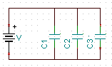
V=V1=V2=V3
C=C1+C2+C3
q=q1+q2+q3
Series method:
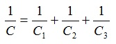
In this method, the potential difference in the entire circuit is equal to the sum of V in each of the capacitors and the inverse of the total capacity is equal to the sum of the inverse of each of the capacitor capacity.
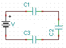
q=q1=q2=q3
V=V1+V2+V3
Series and parallel method:
In this method, like resistors, we first simplify the circuit, then we get the required values with using the relationships.
- Try to avoid putting the capacitors in series and use only one capacitor, but paralleling the capacitors helps to eliminate current noise.
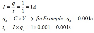
Short circuit and capacitor charging time calculation
If the two pins of the capacitor are connected by a wire, a short circuit occurs and current flows through the wire.
Short circuit also causes discharge of the capacitors.
The time it takes for the capacitor to charge depends on its capacity and the input current (the amount of electrical charge passing per second) and voltage.
For example, a capacitor that can hold 0.001 coulomb charge, when it is discharges in 0.001 second, 1 amp of current passes through it.
Depending on the resistance of the short circuit wire, the discharge time is determined.
The charging time of the capacitors may be longer than this value (depending on the charging source), but approximately we can say that this value is correct. Accurate time calculation can be done with advanced laboratory equipments.
If we use several capacitors in parallel due to the increase in capacity, it will take longer to charge, and if they are in series due to the decrease in capacity, it will take less time.
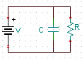
If you want the current to not be completely cut off after charging, you need a parallel resistor with the capacitor.
In this case, after the capacitor is fully charged, the current passes through the resistor only.
Connecting capacitors to each other
If you connect two capacitors together, their voltage will be equal and depends on the following factors:
1- The capacity of each capacitor
2- How to connect the pins of the capacitors
3- Voltage stored in each of the capacitor
The capacity of the capacitors is known and we know the voltage stored in each capacitor; But the pins can be connected to each other in the following two ways:
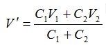
1- Connecting pins of the same poles:
In this case, to calculate the voltage, we divide the sum of charges stored in the two capacitors by the sum of the capacities of the capacitors:
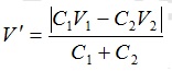
2- Connecting pins with different poles:
In this case, we divide the absolute value of subtraction of electrical charges by the total capacity of the capacitors:
- This feature can be used to transfer charge to capacitors.
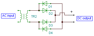
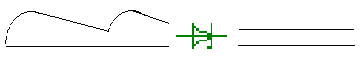
Converting a half-wave signal to direct current with a capacitor
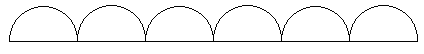
As mentioned in the diode article, the DC current generated from the transformer by the diode is constantly changing, from zero to maximum voltage. To fix this current, capacitors (usually polarized) should be used.
The reason for using capacitors is its charging power.
In this way, when the voltage reaches its maximum, it stores a part of the current in itself and when the current reaches its minimum, i.e. zero, it gradually discharges the current in this interval.
The following figure shows the resulting voltage at a frequency of 50 Hz and a voltage of 10 volts produced by a 100 micro-farad capacitor.
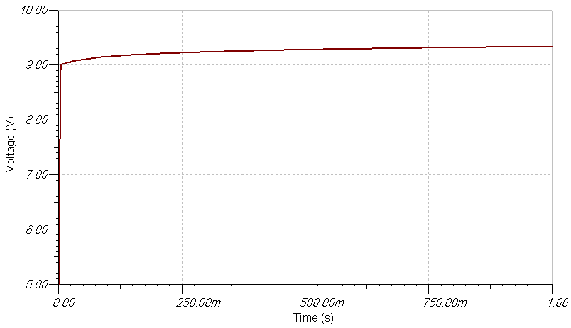
This graph is drawn by an oscilloscope.
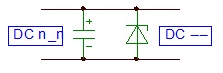
To carry out the action of current continuation, we need to parallel the capacitor with the input.
The figure below shows this process.

- If it is an electrolytic capacitor, its poles must be connected correctly.
To determine the value of the capacitor if the frequency is 50 Hz, the following values can be used according to the voltage requirement of the circuit. These values were also obtained with the help of an oscilloscope.
From 2 to 12 volts, the 100 micro-farad capacitor drops about 1 volt and the current becomes almost direct.
From 2 to 12 volts, 10 nano-farad decrease less than 0.5 volts, and the maximum and minimum current difference is greater.
From these values, it can be concluded that the higher the capacity, gets more direct the current and a higher drop voltage.
- It’s suggested to use both high capacity and low capacity to reduce the noises.
Current stabilizer
You must use a zener diode to stabilize the current.
As mentioned, the zener acts like a resistor in its reverse bias.
When the voltage changes, the value of the zener resistance also changes.
After the zener, to make sure that the current is direct, you can put a capacitor in parallel with the output current.
The following figure shows how to use the zener diode:
- If your power supply current drain is more than the zener limits, use a voltage regulator.
- The zener diode will decrease the final output voltage, for example, a 9v input should be decreased to e.g 8.2v by a zener.
Capacitor in AC current and filter circuit
The performance and features of the capacitors in the AC circuits input is different from DC.
The capacitor can pass the AC current, but only in special conditions.
The following relations determine the ratio between the input resistance and the pass frequency:
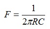
In the above relationship, R is the circuit resistance, C is the filter capacitor capacity and 2π is the pi number (2*3.1415) and F is the maximum frequency (when the parallel capacitor is used) or the minimum frequency (when the series capacitor is used).
In the first moments, the positive charges that is accumulated behind of the first plate of the capacitor cause a negative wind on the opposite plate, and then, with the phase change of the AC input power, the positive charge is discharged from the first plate and replaced by a negative charge, which causes Let the positive charge replace the negative charge on the opposite plate.
This changes cause AC current to drain, but with a 90 degree phase difference. That is, when the sine wave is rising in the first plate of the capacitor, it is falling in the second plate.
But the capacitance of the capacitor limits the current drain, which causes a kind of resistance in the capacitor. This type of resistance is not a heat dissipation type. It does not need to calculate the power, but it must be under the capacitor limited withstand voltage between the two plates.
This feature can also be used for filters.
If we connect the output of the capacitor to the consumer, if the input frequency to the capacitor is lower than the cut-off frequency, by decreasing the frequency, the drain current will be weaker, until it reaches to zero. This is called a high pass filter.
If one pin of the capacitor is connected to the input of the consumer and the other one is connected to the negative, at the cut-off frequency, current is prevented from entering the consumer (such as a parallel resistor) and if the input frequency is lower than the cut-off frequency, less current will be discharged until it reaches to its minimum resistance. This is called a low pass filter.
In the next articles, we will also learn about sound filters (equalizer).
The figure below shows two types of filters.
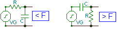
You can use this interesting property of capacitors as a filter in any other way you want.
Filters are also used as non-pass (parallel two filters) and middle-pass (sequential two filters).
Capacitive stabilizer
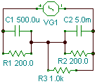
Some parts need a saturation voltage, or for the AC current to pass completely, they need a voltage and a current that make the negative half-waves positive (especially after passing through the capacitor) such as a transistor, which is an example of its application in the amplification of audio frequencies, so current must be given to the input of the component by help of a resistor.
General oscillations may cause problems in the operation of the circuit, so these extra oscillations can be avoided with a capacitor in parallel with the resistor.
The following circuit is an example of this process (R3 is the consumer):
The following diagram shows how the above circuit works against oscillation:
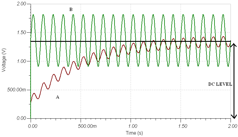
In the A signal, capacitors is used while in the B signal, there’s no stabilizer cap. As you can see, at the beginning, the voltage is increasing due to the charging of the capacitors and then the voltage of A fluctuates less than B.
Practical use of capacitors
Single-LED flashing circuit:
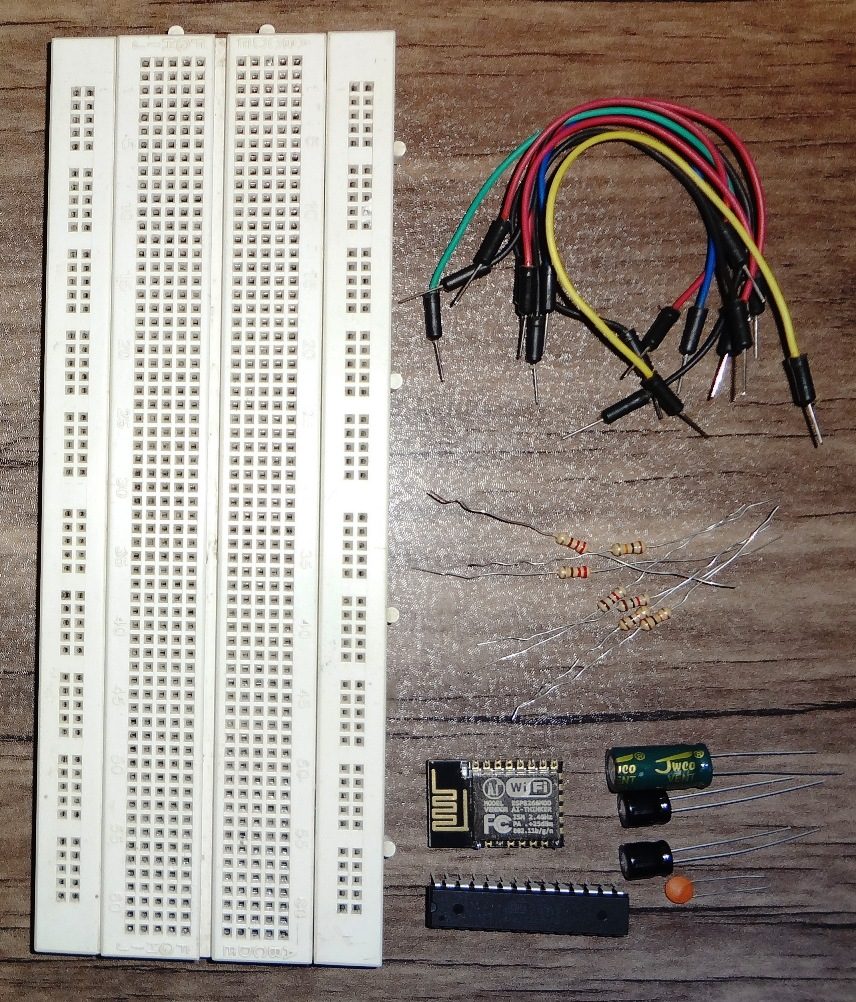
Required equipment: 12 V power supply, switch, LED, 180 and 470 ohm resistor, 1 milli-farad capacitor, 5V relay, some wire.
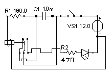
If you mount the above circuit according to the schematic, you will see that after connecting the switch, the LED starts to turning on and off.
Circuit analysis:
The current enters from the positive pole of the power supply to the circuit, then it enters the wire that is connected before the capacitor and reaches the NC pin of the relay, and the current through it reaches behind of the 180 ohm resistor.
After passing through the resistor, the current enters the relay coil pins and the relay will activate, which causes the NO pin of the relay to drain the current and the light turns on.
This is where the capacitor starts charging.
After the capacitor is charged, the relay is disconnected and the light is also turned off, and at the same time, the two capacitor pins are connected to each other by the NC pin of the relay and a short circuit occurs (you can use an additional resistor, e.g. 22 ohm to reduce the discharge time).
After discharging the capacitor, this operation starts again.
- The above circuit is only for the train use and may damage the capacitor and relay in long time usage.
Making an AC to DC adapter using an alternating current generator:
In this picture, VG means alternating current generator.
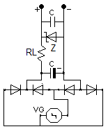
You can add a battery to this circuit and charge it according to what you have learned so far.

Written by: M. Mahdi K. Kanan – Full stack electronics and programming engineer and the founder of WiCardTech