Resistor and how to use it in the circuit (basic electronics)
Resistor prevents additional voltage or current from entering the part in the circuit.
The maximum allowed voltage or current of each part may be different from another part, if it exceeds, It will cause the overheat and the material of that part combines with oxygen and in the other words, the part burns.
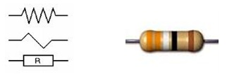
The resistor is a two-pins (non-polarized) part and the unit of resistance measurement is Ohm (Ω).
Short circuit and how to calculate resistances in the circuit
If the two ends of the resistor are connected by a wire, a short circuit occurs and the current passes through the wire (because of the lower resistance of the wire).
To use resistor and the calculations, we need to know the following values:
1- The maximum needed voltage of the component or consumer device (V)
2- The maximum needed current of the part or consumer device (I) at the above voltage
3- The input voltage or power supply voltage
The values which are written on the part label, are the power consumption (P) and its voltage, so we can achieve the needed values from the power consumption of the part with the following relationship:
P = V × I
- In order to obtain the unit of resistor in ohms, the voltage must be in volts (v), the current in amps (A) and the power in watts (W).
After obtaining the mentioned values, we can obtain the amount of resistance that should be placed on the current path (input or output) with using the following relationship:
[Ohm’s Law] R = V / I –> R = (V0 – V) / I
In the above relationship, V0 is the power supply voltage, V is the acceptable voltage of the part, and I is the maximum current required by the part.
- You can use the insertion method to calculate values more easily; For example, use P/V instead of I.
Calculation of the power of the resistor
When using resistors, we must pay attention to the maximum acceptable power of the resistor.
This value obtains with the following relationship:
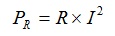
In this relationship, I is the maximum current that passes through the resistor (the consumer needs) and R is the resistance obtained by the previous relationship in ohms.
- Most of the resistors are less than 0.5 watts and the resistors more than 2 watts are too big for a regular circuit, so try to choose the components with less power consumption.
- There is some kind of internal resistance in all parts, which you can consider for more accurate calculation.
Types of resistors and how to get their value
Here are some kinds of the resistors that you can use as adjustable switch, robot sensors, etc. with the help of calculation:
Light resistors (LDR): In these types, the amount of resistance increases or decreases according to the light intensity.
Thermal resistors (PTC): In this type, increasing the temperature increases the resistance.
Thermal resistors (NTC): In this type, increasing the temperature decreases the resistance.
Voltage Sensitive Resistor (VDR): In this type of resistors, their resistance value is greatly reduced in a particular voltage. These resistors are usually installed in the circuit in parallel with the power supply and a series fuse to protect the components.
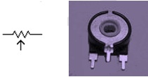
Potentiometer: This type of resistors consists of a carbon fixed part and a conductive movable part and has three pins. Usually the middle pin is connected to the movable part (for current input or output) and the other pins are connected to the carbon part ends. By twisting the moving part of the other carbon, the resistance increases or decreases between the main pin and the other two pins.
Axial Resistors with E12 and E24 standard: these are the common resistors in electronic devices that have 4 or 5 colors. Here we will check the resistance with E12 standard.
E12 resistor
These resistors have 4 colors, the first two colors only include the numbers 10-12-15-18-22-27-33-39-47-56-68-82 (the resistors which first two digits of their value are from the numbers are high available in the markets).
- It is better that the resistor which is used in the circuit design, be more than the calculated value, so there is no need to consider the error factor.
To read the resistance value, we must read it from the side that is closer to the edge (the direction where gold or silver color is not used).
The table below shows the corresponding number for each color:
| Color | First, Second Rings | Third Ring | Fourth Ring |
| Silver | – | 10-2 | 10% |
| Golden | – | 10-1 | 5% |
| Black | 0 | 100 | – |
| Brown | 1 | 101 | 1% |
| Red | 2 | 102 | 2% |
| Orange | 3 | 103 | – |
| Yellow | 4 | 104 | – |
| Green | 5 | 105 | – |
| Blue | 6 | 106 | – |
| Purple | 7 | 107 | – |
| Gray | 8 | 108 | – |
| White | 9 | 109 | – |
A useful way to calculate the resistor value: first we write the number of the rings (1 to 4) from left to right, then we read the resistance colors from the correct direction and write them in one line from left to right (for example: orange, white, red, gold) and fill the third row using the above table; As follows:
1 2 3 4
Orange, White, Red, Golden
3 9 * 100 ± 5%
Value: 3900 = 100 × 39 Error rate: 195 = (3900 × 5)/100
The resistance is 3900Ω and considering the error percentage, its value is between 3705 and 4095 ohms.
So, as a result, the part must have a minimum minimum resistance of slightly less than 3705 Ohms (for example, 3600 Ohms).
Connecting resistors to each other
The method of using resistors in the circuit is very important because by using the correct method, you can make the amount of resistance that is not in the standard and you can use it in the circuit.
You can connect the resistors in the following three ways:
1- Parallel
2- Series
3- Parallel and series
- The use of each of these states causes a change in the voltage and current intensity too, with some very simple calculations (Ohm’s law), these values can be obtained.
- It is recommended to use only one resistor as much as possible instead of series or parallel resistors.
- For the correct connection, the part should be considered in parallel or series with the other resistors. In this case, the internal resistance of the part can be used as a resistor.
Calculation in parallel circuit
In a parallel resistors circuit, we must add the inverse of each resistor values together to get the total value of the resistances. Below are the circuit type and calculation formula:
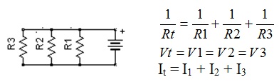
In the parallel circuit, the current intensity of the points closer to the power source is always higher.
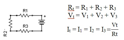
Calculation in series circuit
In the series circuit, we must add the values together to get the total value. Below are the circuit type and calculation formulas.
Calculation of resistance with an example (turning on a 3v lamp with a 12v power supply)
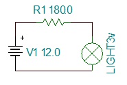
In the circuit above, the lamp needs 3 volts and 0.15 watts power.
The required resistor is calculated with using the following relationship:
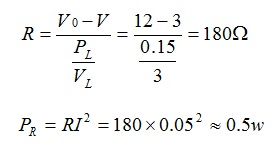
The required resistor is 180Ω (180.0) and its color code is: brown, gray, brown, gold.
The allowed power of this resistor should be 0.5 watts (or more) so that it does not burn itself.
If 0.05 amperes current passes through this resistor, it will reduce 9v of the power supply voltage before entering to the lamp and the lamp will receive a 3v.
The lamp gives the maximum light intensity in these condition without burning due to receiving a large potential difference (voltage).

Written by: M. Mahdi K. Kanan – Full stack electronics and programming engineer and the founder of WiCardTech