Electrical, magnetic and electromagnetic fields
This article first deals with simple definitions related to electric and magnetic fields, then enters the subject of the combination of these two fields, which is called electromagnetism and electromagnetic field.
This article is a continuation of the basic electronics article.
Electrical Field
The Electrical charge
Everything in the world has some kind of gravity: planets, objects, atoms, protons, neutrons and electrons.
But if all these attractions were of the same type and only depended on Newton’s law of gravity, the whole universe would become a very large object; So we can conclude that in addition to the mass gravity, there is also a kind of repulsion to prevent all elementary particles from colliding with each other.
This type of the attraction/gravity and repulsion has been created as a kind of frequency in fundamental particles, which changes the fundamental particle as well.
There are two types from the fundamental particles that both repel their own type and attract the other. These two particles are called electrons and protons. According to the definition, the proton has a positive charge and the electron has a negative charge, the charges of these two particles are equal.
Negative charge
In general, negatively charged objects have more electrons than protons. Since the number of protons in an atom cannot be easily changed, to make an object negative, we have to inject electrons into it.
Positive charge
In general, positively charged objects have fewer electrons than protons. Since the number of protons in an atom cannot be easily changed, to make an object positive, electrons must be taken from it.
Electronic
The science of electronics means stating methods for injecting or taking the electrons form the conductor or semi-conductor materials, and combining mathematical relationships with these methods.
Digital science is the combination of logical relationships with electronic science. Before learning these methods, it is necessary to first address some of the rules between charges, whether they are stationary or moving.
Force between two loads
The charge of each electron is equal to:
1.602 x 10^-19 coulomb
Each coulomb is equal to the charge of 6,242,197,253,433,208,489 electrons that are concentrated in a point.
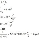
The force between two charges, at two different points at a distance of r, is calculated through the following equation:
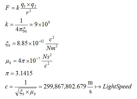
The coefficient of magnetic permeability in vacuum/space is µ0 and the coefficient of electric permeability in vacuum is Ƹ0 and these two values are completely constant in this world as long as the light speed (c) is constant.
The current speed in circuit routes/wires is usually about half of the light speed of light (knowing the accurate speed is very important for high frequency data transmission).
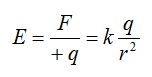
The electric field of a point
The force created by the accumulation of a number of charges (due to the attract force of each charge) in the space around a charged object is called the electric field of a point.
This property causes repulsion of load of the same charge and attraction of the load of the opposite charge.
The following relationship expresses the electric field around the electrons of a point:
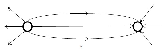
Electric field lines
They are hypothetical lines along which the effects of the electric field take place. You can see these lines in the figure below:
Electric potential (volts)
The energy in a conductive object, a wire or any other conductive material, is called electric potential energy or volts.
You can measure the amount of potential energy in relative to an object with a 0V source (e.g. ground wire) and a voltmeter.
Potential energy is obtained from multiplying force in displacement (W=Fd).
Electric potential difference (voltage)
All the mentioned topics were to convey the concept of voltage.
The difference between the potential energy of two points is called the voltage.
If we connect these two points with conductive wire, the potential energy moves from the higher point to the lower point until the points reach to the same potential energy (e.g. two parallel capacitors).
The unit of potential energy is the same as joule, but in electronics science, due to the importance of the potential difference, it is called volt and voltage.
The speed of moving the charges from the higher point to the lower point is called the electrical current intensity.
- There is no current between two 5V sources, but there is current between a 0V and a 5V source.
Due to the presence of current, there is also resistance.
Magnetic field
In the definition, the hypothetical lines around a magnetic object are called magnetic field.
In other words: wherever there is magnetic property, there is also a magnetic field.
Magnetic property
The property in a magnet is called the magnetic property, which causes magnetic materials (such as iron) to be attracted to it.
The transfer of magnetic properties to magnetic materials is called magnetic induction.
Magnetic materials are divided into ferromagnetic and paramagnetic.
Ferromagnetic materials are divided into two categories: soft ferromagnets (such as iron, which easily acquires and loses magnetism) and hard ferromagnets (such as steel, which takes a long time to acquire magnetic properties and retains this property for a longer period of time).
The paramagnetic materials need a strong magnetic field to acquire the magnetic property, such as Manganese.
Magnetic field lines and its characteristics
A series of invisible lines around magnetic materials. The effects of these lines in the environment can be visible with help of iron shavings.
- To see the location of the lines, you can place a paper on the magnet and spread the iron shavings slowly on the paper.
One of the characteristics of these lines is that these lines never cross each other and in any area where the lines are more compressed, the field is stronger.
The direction of the lines is defined as from the N pole to the S pole (in the inside of a magnet is reverse).
Electromagnetic
The magnetic field can be generated by using the electric current.
The magnetic field which produced by the electric current is called electromagnetic field.
We can use a conductive wire or an inductor to produce an electromagnetic field.
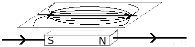
If we pass an electric current through a straight wire, a magnetic field will create around it.
The direction of these magnetic field lines/loops depends on the current direction.
In the picture below, you can see that the current direction is from top to bottom, and the direction of the loops in front of the wire is from right to left:
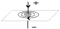
You can determine the direction of the rings in the operating mode with using a compass.
To determine the direction of the field, you can use the right-hand rule in calculations.
If we put two current-carrying wires together, just like if we bring two magnets together, they will exert forces on each other.
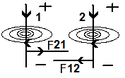
In the picture above, F12 means the field force of wire 1 on wire 2, and F21 means the field force of wire 2 on wire 1.
Now, if we wrap a long coated wire around a rod, after establishing a current, in addition to producing a strong magnetic field, the field of each loop affects on the others.
In this device, which is called an inductor or wire tube, we must use the right hand rule to determine the poles.
Electromagnetic induction
Electromagnetic induction generally is inducting the magnetic field which is made by an electrical magnet (first coil) to another coil, then retrieving the electrical potential in the second coil.
In electromagnetic, from the digital point of view, signal construction is very simple, but from an analog point of view, there are a few complications.
Electromagnetic induction using two straight conducting wires
A straight current-carrying wire can induce an electric current to another wire around it. The reason for this induction is the change in magnetic flux.
In general, changing the magnetic flux means moving the field, rotating the field or changing the strength of the magnetic field.
In the following circuit, by doing the following changes, you can change the magnetic flux and induce electromagnetic induction on conductive objects and surrounding circuits:
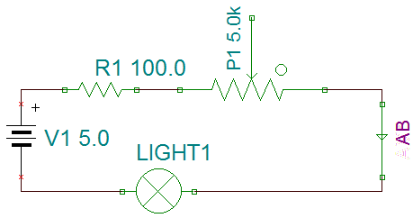
- Moving wire AB
- Rotate wire AB
- Change circuit resistance with P1
When electromagnetic induction is done, to determine the direction of the induced current, we must reverse the direction of the induced field and find the direction of the induced current with using the right-hand rule (lenz’s law).
Coil (inductor)
To building an electrical magnet, if we wrap a wire around an iron nail, and connect the two ends of the wire to a battery, the nail is affected by the magnetic field created by the electric current on the wire and becomes magnetized.
The construction of the coil (inductor) is also the same.
The inductor usually consists of two parts, an iron/ferrite core and a copper wire wrapped around the core.
Inductors can also be without the iron core (air core).
When the current enters the wire, part of the energy is used to create a magnetic field and regularize the magnetic dipoles in the core, which causes the resistance of the inductor to rise at the start and less current to drain out of it, but after the core dipoles are regularized, the resistance of the inductor decreases.
The figure below shows the schema of the inductor:

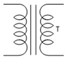
With help of the induce property of the coils, transformer can be made by using at least two inductors. A transformer is a device that can be used to change the input voltage. The transformer has types of step-down (to reduce the input voltage) and step-up (to increase the input voltage). The transformer can only be used in the alternating current.
Electromagnetic induction using an inductor
In the inductor, if we use direct current, the flux changes only when the current is established at the first moment.
But when we use a sine wave alternating current with a constant frequency, we will have a constant magnetic flux change, which causes the magnetic field to spread around in a wave form. This is called the electromagnetic waves.
Each inductor has a self-induction coefficient, with this coefficient and a simple calculation, you can find the amount of voltage drop in the input voltage when the series inductor is used:
XL = 2πfL
π = 3.1415 (pi)
In the above relationships, XL is the resistance created in the inductor due to self-induction in the alternating current.
f is the frequency of the alternating current source,
L is also the coefficient of self-inductance of the inductor, which is usually written on the part.
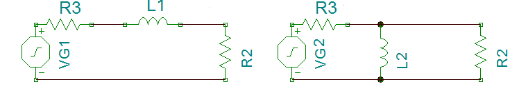
- It is concluded that as the frequency increases, the resistance of the inductor (inductance) will increase, as a result, the inductor L1 in the above circuits plays the role as a low-pass filter and L2 acts as a high-pass filter.
Inductors application
The most important applications of the inductor are the filters and the magnetic/electromagnetic field generators.
Speaker:
You must know that the work of the speaker is to produce sound by vibrating its round and elastic plate. This plate vibrates with using the magnetic force.
An inductor is stuck behind this plate and there is a magnet in the middle of this inductor. By establishing a current to the inductor, the magnetic field exerts force on the inductor and causes the inductor and the plate to move.
The plate moves the air around of itself and the becomes low and high pressure due to the vibration of the plate with an alternating current.
Microphone:
A type of microphone has the same structure as a speaker, the plate vibrates with the air pressure difference due to the sound and causes the inductor to move.
These movements of the inductor with its magnetic constant core presence a magnetic field and electrical potential energy.
Radio communication:
To transmit data through the radio waves, it is necessary to increase and decrease the electric potential in a coil and on the antenna.
This creates an electric field on the antenna, and the movement of electrons in the oscillator components (coil) creates a magnetic field.
The electric and magnetic field, in the form of an electromagnetic wave, spherically spreads around at the speed of light.
These waves can be received and retrieved by coils and antenna, and then amplified and decoded by the receiver circuit.
In the future articles, I will talk about how to send and receive data with the electromagnetic waves.

Written by: M. Mahdi K. Kanan – Full stack electronics and programming engineer and the founder of WiCardTech