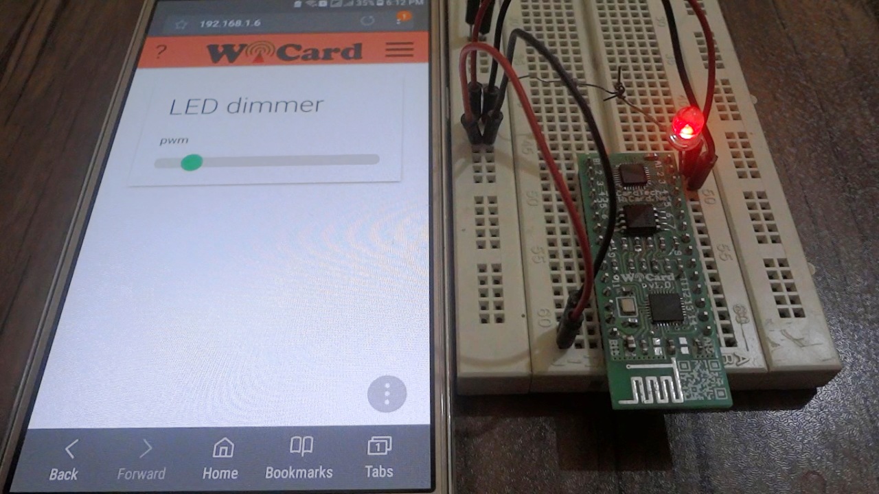
PWM Amplifier

This project is a PWM amplifier suitable for the arduino boards.
In the project files, there’s its schematic plan and its PCB plan.
also there’s a manual file which helps you to build and use the project.
You can use this amplifier project as the RGB Driver project amplifier.
PWM Amplifier Circuit Specifications
The amplifier circuit of this project, according to the parts, needs 3-6 mA input and is able to drain 5A.
The active state is “LOW”, for example if the consumer is a power LED, the positive pin (Anode) must be connected to the + of the power source, and the negative pin (Cathode) must be connected to the amplifier output.
Con1 is the inputs connector, Con2 is the outputs connector and Con3 is the amplifier’s power connector.
The standard working voltage is between 5 to 12 volt, but the parts are able to support 16 volt.
The output has 3 separate channels and is useful for 3 phase motor driver, RGB LED driver, DC motor speed control, robots and etc.
This circuit is also compatible with “Arduino UNO” or other 5V boards/MCUs but the power source of amplifier must be 5V and the power source of consumer can be vary between 5-12V.
The project is available in the following:

Written by: M. Mahdi K. Kanan – Full stack electronics and programming engineer and the founder of WiCardTech

5 Responses
Greetings, I do believe your blog could possibly be having
browser compatibility problems. Whenever I take a look at your blog in Safari, it looks fine however,
if opening in IE, it has some overlapping issues. I simply wanted to give you a quick heads up!
Apart from that, fantastic site!
Thanks!
Normally I do not learn post on blogs, however I would like to
say that this write-up very compelled me to take a look at and do
so! Your writing style has been surprised me. Thanks, quite nice
post.
You’re welcome
Hi it’s me, I am also visiting this website daily, this site is really fastidious and the visitors are actually
sharing nice thoughts.