WiFi RGB driver With Two Channels and Light Flashing program
The WiFi RGB Driver receives the commands from the user via WiFi with ESP8266 and the web page, then sets the duty cycle of PWM signal and sends it to the MOSFETs and sets the light intensity of two separate RGB channels.
You’ll be able to set a constant color for the RGB lights in thousands of color. Also you can enable the flashing program and define unlimited scenarios for the RGB lights.
Also with the microphone which is placed on the driver’s circuit, the driver is able to flash the LEDs according to the music rhythm.
This project contains three folders: ESP8266WiFiRGB (the arduino source code), PCB-SCH-BOM (the plans) and PHP Script (for server use and portforwarding).
The project link: Source code, PCB and Schematic Plans of 2 ch WiFi RGB Driver With Flahing Program and Sound Processor
The plans folder contains these files:
- “Altium Designer” PCB file
- “Altium Designer” Schematic file
- “DipTrace” PCB file
- PDF Schematic and PCB
- BOM
The source code folder contains these files:
- ESP8266WiFiRGB.ino the main program
- AC.ino WiFi configuration program
- AC.h WiFi configuration header file
- RGBPage.ino UI file
- RGBProg.ino RGB processor file
- SavingData.ino EEProm file
- Settings.h driver’s settings file
First open one of the files with Arduino program, then set the settings (Board, CPU Frequency and Flash Frequency).
- The compiler of software (board) must be set on the “Generic ESP8266 Module” (or similar) before doing anything.
Then put the ESP8266 module on the “download mode” and upload the program.
After upload, run the program in “normal mode”.
Then in case you are using ESP12, the blue LED on the board would be turned on for 1 second then turns off. Then you’ll be able to see the module’s hot spot ssid via the WiFi networks in your PC or smart phone.
WiFi RGB Driver Configuration
The default SSID is WiCardRGB and the default password is 12345678. Connect and go to 192.168.4.1/config with a web browser.
The WiFi autoconnect configuration page:
In the “Modem Configuration” section, you’re able to view/edit the SSID and password of WiFi modem/router and then click on “Save” after inserting. The module would connect to the modem after about 30 seconds in case of validity of ssid and password.
- This page is also available via the DHCP IP of the module.
In the “Device Hot Spot Configuration” section, you can set the module hotspot’s SSID and password. Also you can set a password for the internal page with Secure Link section. (Example: the secure link is ABCD and the root page would be at 192.168.4.1/ABCD/ address)
The “Hidden HotSpot” button will set the module’s hot spot as hidden hotspot and the “Disable HotSpot when is connected to the modem” would disable the module’s hotspot, when is connected to the modem.
The Main Page of WiFi RGB Driver
This page is in the root address (192.168.4.1 or the router’s given IP) and with two color circles you can set a constant color for each channel.
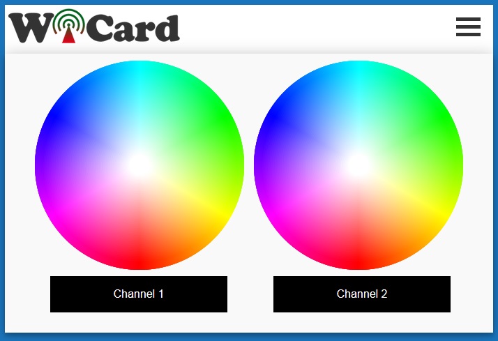
With touch or click on any point of the circles, the color of that channel will change and the result will be shown in the rectangles blow of the circles.
With click or touching the rectangles, the LEDs of that channel will be turned off.
- If you are using mobile browser, to scrolling the page, touch and hold the rectangles and then scroll the page.
Menu Items
The menu button is in the top-right of the page. The items are:
- Home or Refresh: the main page’s link
- Program: the program page’s link
- Settings: the white balance page link
- WiFi Configuration: modem and hotspot settings
- Our website link
White Balance
In the white balance page, there are three sliders for each channel to set the white color of the RGB LEDs.
With enabling “Load The Last Light Mode When Power On” option, the driver will turn on in the last state. Otherwise it will turn on in the off state.
Program Page
In this page you are able to define unlimited flashing scenarios for the WiFi RGB Driver:
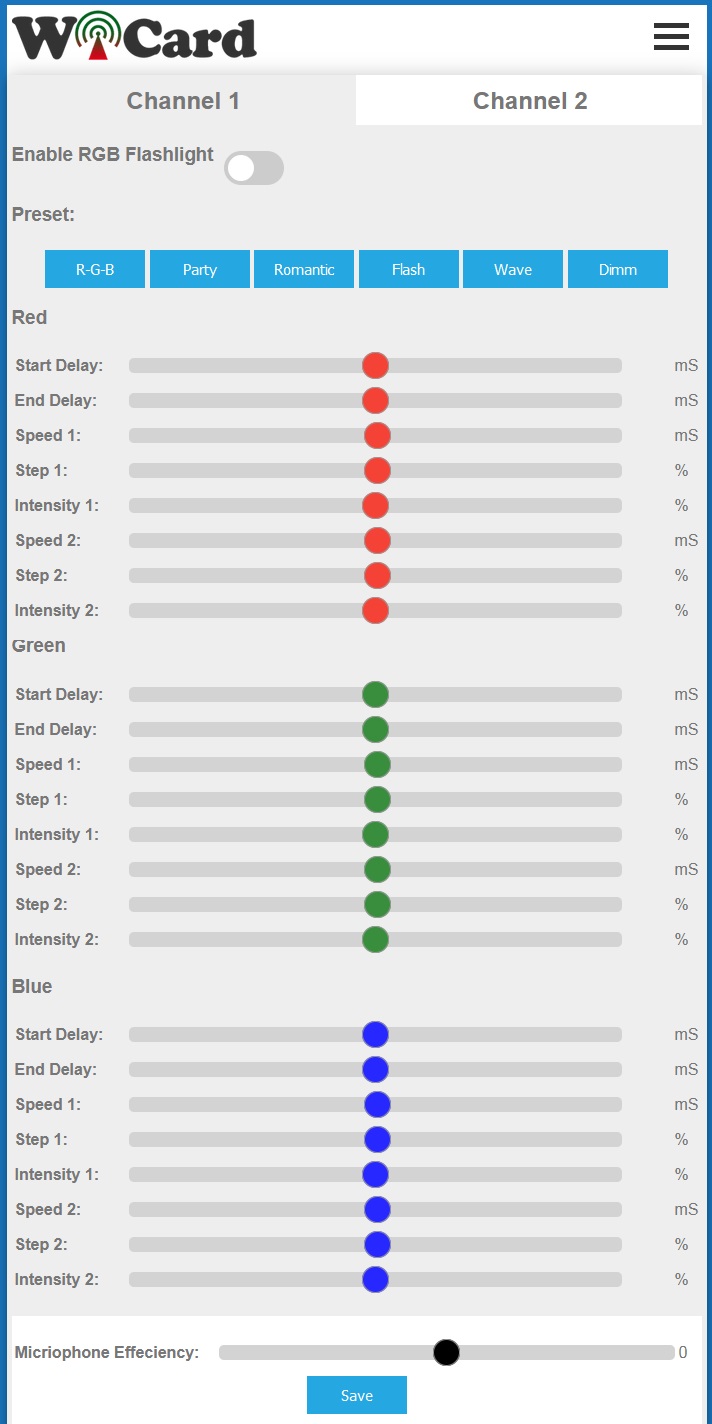
In the top of the page there are two tabs which let you choose the desired channel.
The “Enable RGB Flashlight” button enables and disables the RGB flash light scenario player.
There are six preset scenarios:
R-G-B: turns on and off the Red LEDs, then Green LEDs and then Blue LEDs
Party: different colors will change rapidly
Romantic: the colors will change slowly
Flash: the colors will flash
Wave: the colors will change wave-ly
Dimm: the colors intensity will change slowly
Also there are three sections for manual programming of the Red, Green and Blue outputs for each channel:
Start Delay: the scenario’s start delay
End Delay: the scenario’s delay after end
Speed1: speed of the first intensity change
Step1: step of the first intensity change according to the speed
Intensity1: the first desired intensity
Speed2: speed of the second intensity change
Step2: step of the second intensity change according to the speed
Intensity2: the second desired intensity
The “Microphone Efficiency” slider can be set between 0 to 10 and sets the efficiency of sound processing to the RGB flashing program.
With a music stream and enabling these features, you’ll experience an exciting lighting.
For the slow music use slow scenario and for the EDM music, the best choice is R-G-B, Party or Flash presets.
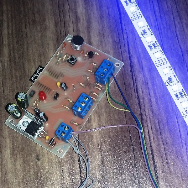
The WiFi RGB Driver Circuit
The circuit contains three connectors, a push button and two pin headers:
The Con1 connector has Red (R1), Green (G1) and Blue (B1) outputs of the channel 1. Tie the positive (Anode) pins of the RGB LEDs to the + of power source and connect the negative (cathode) pins to the R1, G1 and B1 outputs.
The Con2 is for the channel 2.
The power source of the driver must be connected to the Con3.
With pushing the button, the state of flashing will change. With holding this button for 10 seconds, LED1 will blink for 3 times and the driver will set to the default settings.
The H1 pin header is for program upload. Pin 1 (square) is the module’s TxD and pin 2 is RxD.
And the H2 is for program upload and must be connected with a jumper before turning the driver on for the program upload mode.
- Use a standard 2A and 5-12V power source.
- Each output can drain 1A max.
The PWM Amplifier
If case of using much RGB LEDs with more than 1A current consumption, use a PWM Amplifier Interface to increase the output capacity.
Connect the three inputs of the amplifier to one of the RGB channels. Then tie the positive (Anode) pins of the RGB LEDs to the + of power source and connect the negative (cathode) pins to the amplifier’s outputs.
Source Code Manual
In the AC.h file, if you remove “#define LOG_ENABLE”, the logs will not be show and the log memory would be release.
With add or remove “#define UPDATE_IP” you can enable or disable the server connection option.
If you have not enough programming and electronics knowledge, do not make changes.
The project is available in the following:

Written by: M. Mahdi K. Kanan – Full stack electronics and programming engineer and the founder of WiCardTech