Programmable WiCard WiFi Module
In the ESP8266 WiFi Module article, I introduced the ESP8266 module and a sample circuit with this module and ATmega8a which is called WiCard.
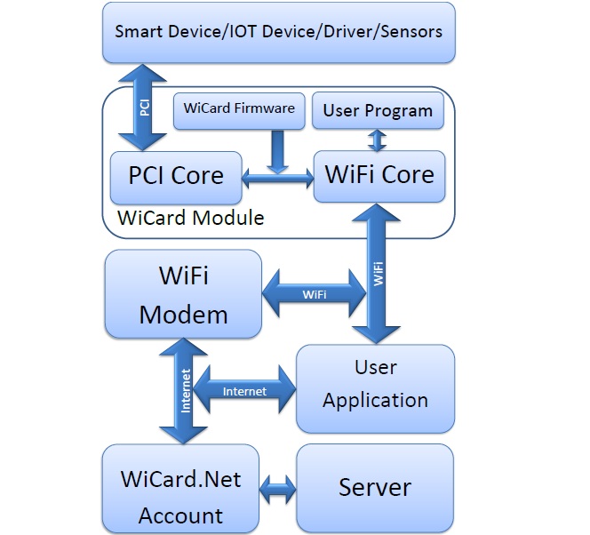
The WiCard WiFi Module Description
The WiCard WiFi module has two cores, one of the cores controls WiFi connections between the module and server/user application. Also this core parses the user program for the other core. The other core directly controls peripheral components such as Inputs, Outputs, PWM and etc.
How To Use
After plugging the module to 3.3V source (VCC and GND pins), The WiFi core turns on its access point and user will be able to see the module’s SSID. The SSID of WiCard module starts with “WIC” and the default password is “0123456789”. So after connecting to the access point of the module, User is able to configure the module with using a web browser and the internal IP of WiCard “192.168.4.1” (Like WiFi routers configurations page). In the configuration page, there is a settings section for setting WiFi router’s SSID and Password. So after the module gets its IP from the WiFi router, it will contact with WiCard.Net servers to getting the initial data and information.
For programming a WiCard module, there is an online compiler application and simulator on the module’s panel. Furthermore, there’s a free “on web” compiler on the “simulator page” and user is able to export a program file from it and upload it into the module manually whether the WiCard WiFi module is registered or is using a free trial firmware.
Therefore, the user is able to make a “Control Box” for the module with the online compiler. Control Box contains “Toggle Buttons”, “Sliders”, “Push Buttons”, “Peripheral Objects Controllers”, “Source code” and etc. After compiling the program, the program code will be uploaded automatically on the module. The Control Box will be saved to the module control panel on the server and also to the memory of the module for direct access from the WiCard access point.
How to program
For example user puts a toggle button on the control box and sets it for “PORTBit_0”. Then after uploading the program on the module, with toggling the button on the Control Box, Pin of PORT Bit 0 will set on High level (3.3V) or Low level (0V).
Applications
- IoT Devices
- Home Appliances
- Home Automation
- Security Systems
- Smart Plug and lights
- Industrial Wireless Control
- Central Infrared Remotes Controllers
- Controllable Devices
- Sensor Networks

Written by: M. Mahdi K. Kanan – Full stack electronics and programming engineer and the founder of WiCardTech