WiCard ADC (+Tutorial Video)
With help of my project, ESP8266 and ATmega8a (WiCard) module, you can build this adc project.
WiCard ADC (Analogue to Digital Converter)
There are 22 lines of the pins available for the user to program in WiCard WiFi module. 8 of these lines can be set as “Analogue to Digital Converter” (ADC) input.
| PIN | Port Bit | Analogue to Digital Converter |
| A01 | VCC 3.3v | |
| A02 | Ground | |
| A03 | 0 | |
| A04 | 1 | |
| A05 | 2 | |
| A06 | 3 | |
| A07 | 4 | |
| A08 | 5 | |
| A09 | 6 | |
| A10 | 7 | |
| A11 | 16 | * |
| A12 | 17 | * |
| A13 | 18 | * |
| A14 | 19 | * |
| A15 | 25 | |
| B01 | 24 | |
| B02 | 23 | * |
| B03 | 22 | * |
| B04 | 21 | * |
| B05 | 20 | * |
| B06 | 15 | |
| B07 | 14 | |
| B08 | 13 | |
| B09 | 12 | |
| B10 | 11 | |
| B11 | 10 | |
| B12 | 9 | |
| B13 | 8 | |
| B14 | Ground | |
| B15 | VCC 3.3v | |
The ADC data resolution is 10 bit. Also the reference voltage (In the current revision of the firmware 1.0.1) is 2.56v.
The Functions:
Currently there are two functions for Analogue to Digital Converter:
- ConfigurePinAsADC(ucSettings[7:6] | ucChannel[4:0])
This function needs an 8 bit argument which the first 5 bits sets the ADC channel. Furthermore the last 3 bits sets the configuration of ADC. After calling this function, the PCI core will start converting the signal on channel. So to using an Analogue to Digital Converter channel, always this function must be called.
Currently, configuration bits must be set as 110, That means:
To reading Analogue to Digital Converter data from channel 16, the argument must be 0xD0.
Also 0xD1 for channel 17.
0xD2 is also for channel 18.
0xD3 is also for channel 19.
0xD4 is also for channel 20.
0xD5 is also for channel 21.
0xD6 is also for channel 22.
And 0xD7 for channel 23.
- uiReadADCBuffer()
This function returns a 32 bit value of ADC data, but the ADC data is a value between 0 – 1023 (10 bit).
Example:
ControlBoxHandler()
{
    ConfigurePinAsADC(0xD6); // ADC Channel 22, Pin B03, Port Bit 22
    musFeed_0 = uiReadADCBuffer();
}
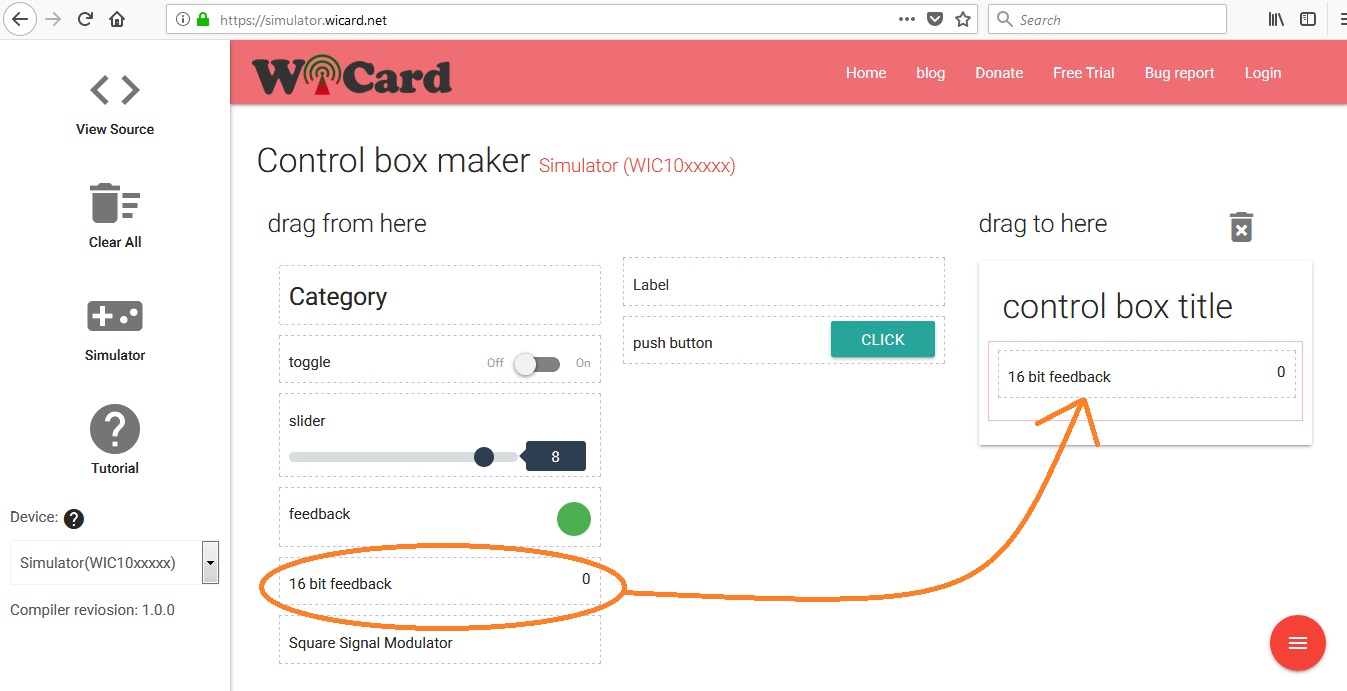
The 16 Bit Feedback:
In the WiCard simulator page there is a “16 bit feedback” tool which is able to show a number between 0 and 65535 (an unsigned 16 bit integer). To using this tool, simply drag and drop the item into the control box.
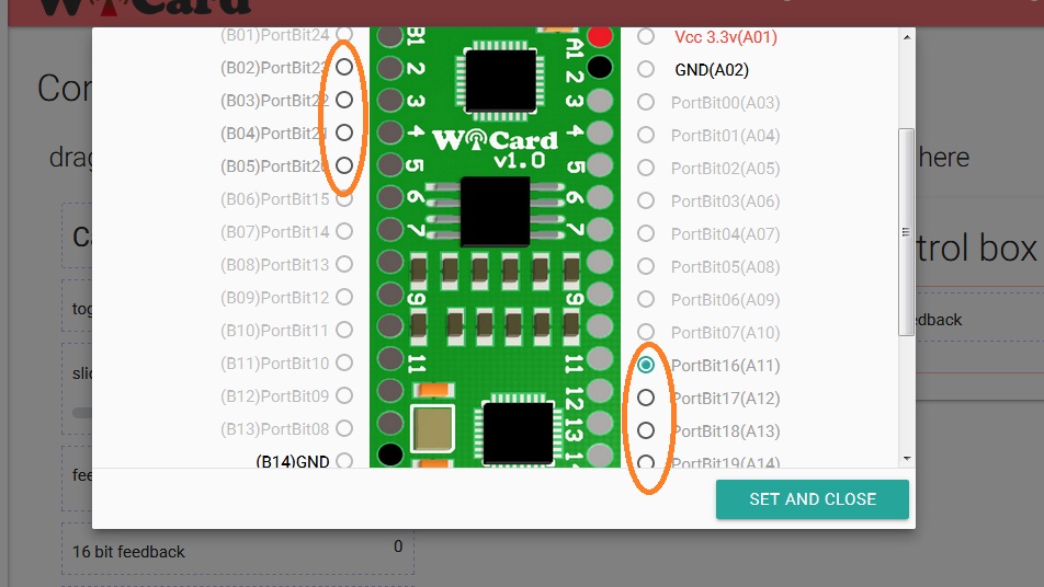
Then double click on it and select the channel that you want to set its ADC data on the feedback.
Tutorial Video:
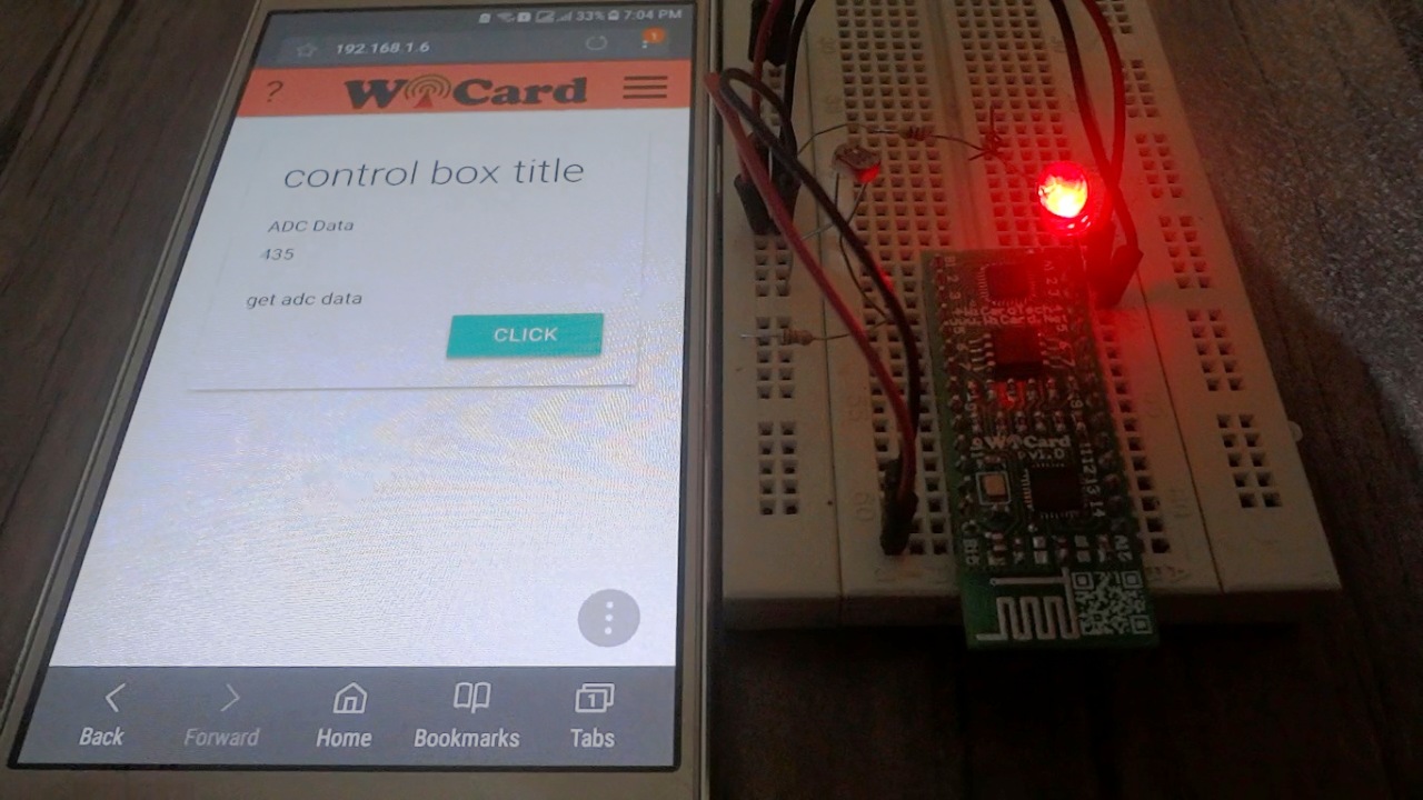
This video will show you how to set a “16 bit feedback” item on an ADC channel of WiCard.
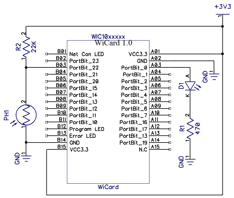
For example in the above video, the pin B03 (ADC 22) reads the Analogue to Digital Converter data from an LDR sensor. Here’s the schematic:

Written by: M. Mahdi K. Kanan – Full stack electronics and programming engineer and the founder of WiCardTech