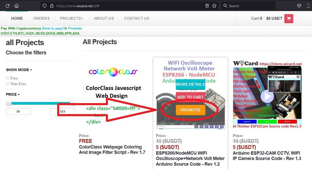
Tag: atmega8a

WiCard - Smart Programmable WiFi Controller Module

wifi robot esp32-cam

WiFi Robot (3-Wheels) With ESP32-Cam and ATmega8A

This project is an “ESP32-Cam WiFi Robot” firmware arduino source code (.ino) and also can be used as a “Dome Camera”. This project is based on the “ESP32 WebApp Builder” and Arduino ESP32-CAM CCTV, WiFi IP Camera projects. The WiFi Robot project uses the “AI Thinker ESP32-CAM” module which has a 2MP Camera, 10 I/O…
Read more

battery charger circuit

Battery Charger Circuit (1.5-24V) With ATmaga8A – Code and Plans

The main processor of the “1.2-24V Battery Charger Circuit” is ATmega8A. ATmega8A is an AVR 8 bit microcontroller which has 28 pins. This circuit has an internal volt-meter and temperature-meter with digitally calibration feature. The project contains 3 folders, “CodeVision Source”, “PCB-SCH-BOM” and “sim”. The project’s link in our online store: The Source Code, Schematics…
Read more

alarm clock calendar

Alarm Clock, Calendar and Temperature Meter With AVR ATmega8A

ATmega8A is an AVR 8 bit microcontroller which has 28 pins. The “Alarm Clock And Calendar” project uses this microcontroller as its main processor and a standard 16×2 Character LCD without using any additional module. There’s a source code folder in this project which contains the CodeVision program files (C) and pre-compiled HEX file. To…
Read more

wicard breadboard

Make Your Own WiCard On A Breadboard

Like “Arduino”, you can make your own WiCard on a breadboard. If you want to make WiCard on a breadboard before making the PCB, all you need is some resistors and capacitors, a breadboard, wires, an ATMega8a (DIP), an ESP8266 module (with a 32 Megabit flash memory).   The Schematic Here’s the connections guide:  …
Read more

wicard timer 1

WiCard Timer (+Tutorial Video)

WiCard 32 Bit Timer There’s a 32 bit timer counter in WiCard WiFi module. The timer calls its handler function whenever its counter reaches to 0. The unit of the timer counter is micro second (uS). This feature in the current revision is limited. So the real time unit is 1000 uS. That means the…
Read more

wicard adc

WiCard ADC (+Tutorial Video)

WiCard ADC (Analogue to Digital Converter) There are 22 lines of the pins available for the user to program in WiCard WiFi module. 8 of these lines can be set as “Analogue to Digital Converter” (ADC) input. PIN Port Bit Analogue to Digital Converter A01 VCC 3.3v A02 Ground A03 0 A04 1 A05 2…
Read more

wicard pcint feedback

WiCard PCInt (+Tutorial Video)

WiCard PCInt (Pin Change Interrupt) There are 22 lines of the pins available for the user to program. You can set 20 of these lines as logical input (GPI) and interrupt (PCInt). Also you can set 19 of them as logical output (GPIO). PIN PortBit Rising Edge Interrupt Falling Edge Interrupt A01 VCC 3.3v A02…
Read more

wicard gpio toggle

WiCard GPIO (+Tutorial Video)

WiCard GPIO (General Purpose Input Output) There are 22 lines of the pins available for the user to program. 20 of these lines can be set as logical input (GPI) and interrupt (PCInt). Furthermore 19 of them can be set as logical output (GPIO). PIN Port Bit Input Output A01 VCC 3.3v A02 Ground A03…
Read more

WiCard Configuration And Settings (+Tutorial Video)

WiCard Configuration, Settings and Internal Page Every WiCard has an internal page for settings, program and configuring the module. The default page address is 192.168.4.1. In this article we talked about how to configure your WiCard module. Also watch the tutorial video.   First Configuration To turning the WiCard on, plug both VCCs (A1,B15) to…
Read more

wicard pwm slider

WiCard PWM (+Tutorial Video)

WiCard PWM (Pulse Width Modulator) The WiCard has 19 PWM lines which are able to be set at the same time. The following table shows which pins are able to be set as PWM: PIN PortBit Pulse Width Modulator Output A01 VCC 3.3v A02 Ground A03 0 * A04 1 * A05 2 * A06…
Read more