Capacitor applications in the circuit design
In the previous articles, I introduced the capacitor and its calculations. This article is about some examples of capacitor applications and how to use it in the circuit design.
Circuits are generally divided into three categories: digital, analog or combined. The role of capacitors in each of these circuits is different, but the function of the capacitor is constant. That is, the plates of the capacitor pass the current at the first moment of its entry. And after that, they store electric charges and block their passage (in a DC current).
For example, as mentioned in the previous article of the capacitor, even the sinusoidal signal that passes through the capacitor has a phase difference. The capacitance of the capacitor also creates a type of resistance that is not the heat dissipation type (Reactance).
Capacitor applications in a digital circuit
Every circuit has a voltage range. For example, between 0 and 5 volts. A digital circuit is a circuit which the components generally have an output of either e.g. 0 volts or 5 volts. For example, the voltage of 2.5 and … does not have a specific meaning in it and should be defined as logical 0 or 1.
For convenience, low voltage (ground/GND/0V) means 0 in the theory of circuit, and high voltage (VCC/5V) means logical 1.
The capacitors applications in digital circuits is mainly as a decoupling filter to reduce the noises or as the clock oscillator capacitor.
In the other words, no signal is completely linear. There is always some, even very slight, voltage fluctuation and noises.
These voltage fluctuations are sometimes in the range of micro-volts. But it may also enter a large swing for a few thousandths of a second and move to the logical range of 0-1.
To prevent this from happening, capacitors are used as noise absorbers, which are called “decoupling”. One pin of the decoupling capacitor must be connected to the signal line, the other must be connected to the ground.
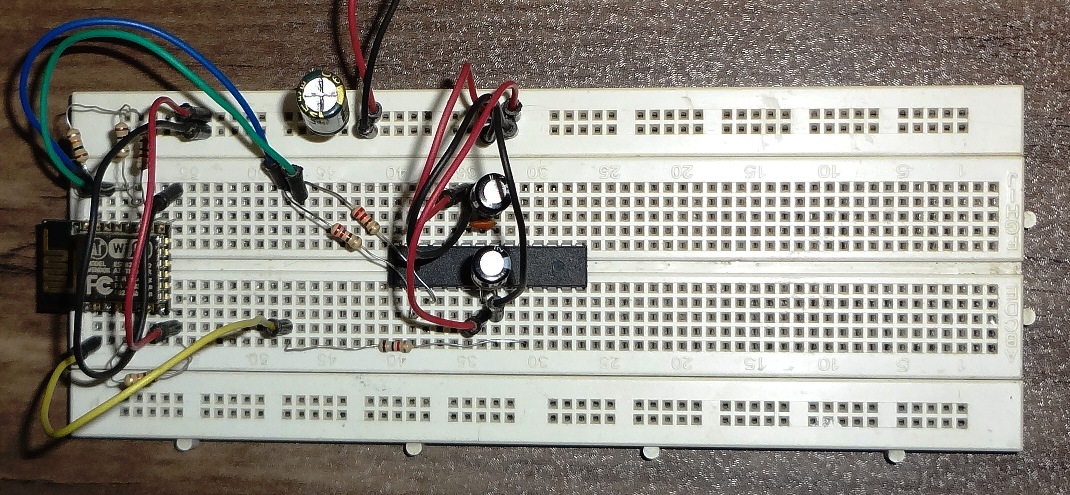
Look at the following circuit:
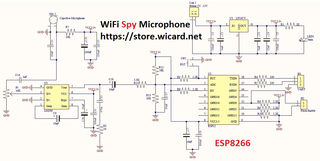
The upper part is the voltage regulator block, which converts the voltage between 5 and 12 volts to 3.3 volts for the other components.
It is clear that this voltage conversion will introduce some amount of noise in the circuit. Therefore, regulator manufacturers always recommend to use decoupling capacitors for the input and output of the regulator.
For the input, two capacitors of 1 milli-farad and 100 nano-farads is used.
The 1 milli-farad capacitor is placed for two purposes of supplying sudden currents that the parts need and also to eliminate low frequency noises.
The capacitor of 100 nano-farads is used to eliminate the high frequency oscillations/noises that may have been created in the path of the adapter to the regulator.
The input must be a standard 12V DC, so two capacitors are enough for the input. But a larger number is used in the output of the regulator.
Three filter stages of 1mF to supply current, 22µF to eliminate mid-frequency noises, and 100nF have been used to eliminate high frequency noise.
Also, at the input of the U2 module, which is pin 8, two more decoupling capacitors have been used to eliminate the path noise from the regulator to the module. In the PCB circuit, these two capacitors must be very close to pin 8 to be enough effective.
A capacitor is also used for the pins of the switches, and it is better to use a capacitor with a relatively low capacity. For example, it is better to place a capacitor between pin 1 of the SW1 key and ground (0 V).
With considering that the time to press the key is about half a second, a capacitor between 10 and 100 nano-farads is suitable.
A lower capacity capacitor is using for less time and a higher capacity capacitor is using for more time
Capacitors in an analog circuit
The relationship between the frequency passing through the capacitor, the capacity and the resistance (Reactance) is as follows:
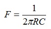
In the above relationship, R is the Reactance, C is the capacitor value in farads and 2π is the 2*pi number (3.1415) and F (cut-off frequency) is the maximum frequency (for the parallel capacitor) or the minimum frequency (for the series capacitor).
In the first moments, the positive charges are accumulated behind the first plate of the capacitor. They cause a negative wind on the opposite side, and after that, by changing the phase of the AC input power, the positive charge discharges from the first side and replaces by a negative charge.
The positive charge cause to replace the positive charge to negative charge on the opposite side.
This changes the charge of the input AC current, but with a 90 degree phase difference. That is, when the sine wave is rising in the first plate of the capacitor, it is falling in the other plate.
But the capacitance of the capacitor limited for draining the current, which causes the “Reactance”.
This feature can be used for the frequency filters.
If we connect the output of the capacitor to the consumer, if the input frequency to the capacitor decreases to the lower than the cut-off frequency, the current drain will decrease until it reaches zero. This is called a high pass filter.
If one end of the capacitor is connected to the input of the consumer and the other end is connected to the ground, at the cut-off frequency, the capacitor starts preventing the current from entering to the consumer by passing it from itself.
If the input frequency increases, less current drains to the consumer until no zero. This is called a low pass filter.
The figure below shows two types of capacitor applications as filters:
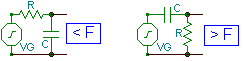
You can use this interesting property of capacitors as a filter in any other way you want.
Filters are also used as non-pass (parallel two filters) and pass (sequential two filters).
In the circuit schematic (Spy Microphone), C14 is a low-pass filter and C13 is a high pass filter.
In general, it is difficult to calculate the exact capacity of the filter capacitor in theory. Therefore, the best method is to calculate the estimated range and finding the best cap by testing different capacitors in the calculated range with using a measuring tool.
The best measuring tool in this field is an oscilloscope that displays the shape of the signal

Written by: M. Mahdi K. Kanan – Full stack electronics and programming engineer and the founder of WiCardTech