WiFi Robot (3-Wheels) With ESP32-Cam and ATmega8A
This project is an “ESP32-Cam WiFi Robot” firmware arduino source code (.ino) and also can be used as a “Dome Camera”.
This project is based on the “ESP32 WebApp Builder” and Arduino ESP32-CAM CCTV, WiFi IP Camera projects.
The WiFi Robot project uses the “AI Thinker ESP32-CAM” module which has a 2MP Camera, 10 I/O pins, an on-chip LED and one MicroSD slot to store the images and videos as the main processor which with its tiny sized camera and 240MHz CPU is able to provide a fair quality images and video frames.
The other core is an ATmega8A AVR microcontroller. This chip controls 4 relays of two motors (in two directions) and communicates with ESP32-Cam via UART pins.
The project contains a schematic file and 2 folders, “ATmega8ARobot” which is the AVR-CodeVision source code and “ESP32CamRobot” the following files:
- ESP32CamRobot.ino (Main handler file)
- AC.h (Configuration header file)
- AC.ino (Configuration handler file)
- functions.ino (System functions)
- rootPage (UI handler file)
- user_global.h – Project global variables and definitions file.
- user_init.ino – Project initial script file.
- user_loop.ino – This file has a “userLoop()” function which calls repeatedly (like arduino “loop()” function).
- user_settings.ino – Project settings file.
- user_main.ino – Online video stream handler script.
- user_sub.ino – Memory handler script.
- user_global.ino – This file has a “userGlobal()” function.
- Webapp.h – This file contains the IPCam WebApp’s script.
The pre-compiled .hex file of the AVR source code is placed in “ATmega8ARobot/Exe/ ATmega8ARobot.hex”.
WiFi Robot Motors
There are different types of DC motors for project like this. I have chosen two 3-6 volt DC motor (which is called “TT Motor”) with gearbox.
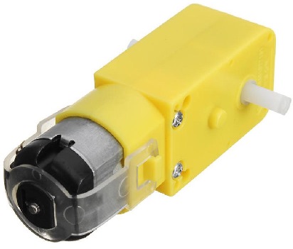
One must be placed in the left side and one in the right side (back or front). A 360 Degree wheel must be placed in the center of the chassis.
The mechanism is so simple:
- When both of the motors are turning with the same speed (with the same voltage and opposite angular direction, CW and un-CW), the chassis will move forward or backward depending of the position of the motors.
- When the motors turn in the same directions (CW or un-CW), the chassis will turn right or left.
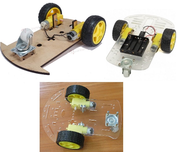
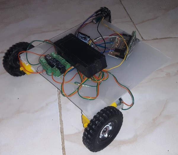
The 3-Wheels WiFi Robot Chassis
You can either use a “DIY 3-Wheels Robot Chassis” (which are available everywhere in different shapes/types) or build a Chassis yourself.
Simply I’ve made a chassis with what I had in my room for this project: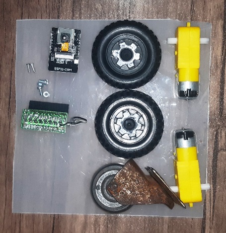
Uploading the project
First open one of the files with Arduino program, then set the settings (Board and Flash Frequency).
- The “Board” must be set on one of the ESP32 Modules before doing anything.
- The start-up CPU speed has been set to 160MHz.
- For the “download mode”, use a jumper for connecting “IO 0” to the GND.
Then turn on the ESP32 module in the “download mode” (GPIO0àGND) and upload the program with using an USB2Serial module.
To uploading the .hex file into ATmega8A, you can use either a standard AVR programmer or our designed AVR programmer, WiCard Kit 1.
- The ATmega8A fuse high byte must be 0xB9 (SPIEN, BOOTSZ1 and BOOTSZ1 are programmed).
- The ATmega8A fuse low byte must be 0xE4 (SUT0, CKSEL3, CKSEL1 and CKSEL0 are programmed).
Preparing The ESP32-Cam WiFi Robot
Build up the chassis by assembling the motors and wheels, upload the firmware in both of ESP32-Cam and ATmega8A and make the circuit according to the schematic file in the project and your chassis.
The best place for the camera is the center-front of the chassis, but I’ve placed it in the left side.
The main power source must be 5V. If your battery or power source has more nominal voltage, use a 5V linear regulator like 7805 or LM2590 Switcher regulator.
Also you can stick a heat sink to the ESP32-Cam’s regulator. It’s not necessary but recommended.
- The onboard ESP32 module must only receive 3.3v. Higher voltage will hurt the module.
- Do not use higher voltage for the 5V and 3.3V input pins.
- You can use this project as a “Dome Camera” with a different movement mechanism.
- You can insert a micro SD memory in the ESP32-Cam memory slot to record videos or taking pictures.
- Do not insert or remove the memory card when the module is turned on.
- When the LED blinks multiple times, that means an error occurred (either memory error or camera error).
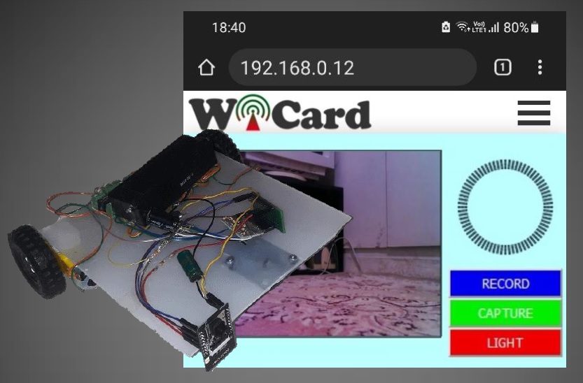
The WiFi Robot (or Dome Camera) Web Application
Build the robot or dome camera according to the schematics and upload the programs. Then turn it on.
The LED will blink once (in case of everything is ok-or multiple times in case there’s no memory card). Then you’ll be able to see the module’s hot spot ssid via the WiFi networks in your PC or smart phone.
The default SSID is WiCardRobot and the default password is 12345678. Connect and go to 192.168.4.1 with a PC or smart phone web browser (Chrome or Firefox).
Here’s the web UI:
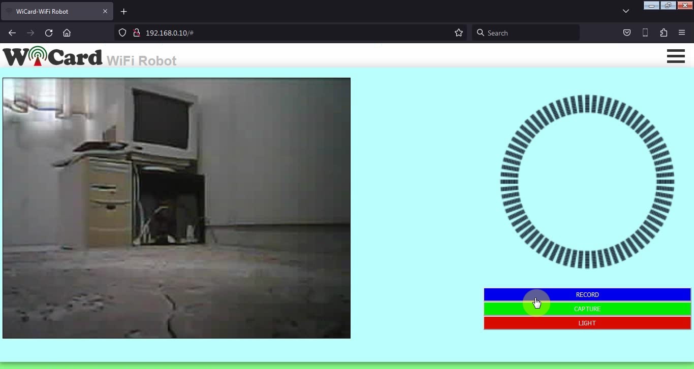
There are driving and recording tools in the right side. By tap or click on the steer, you can drive your robot.
In case of inserting memory card, by tap or click on the “RECORD” button, it starts recording video (the button’s name will change to “STOP”).
By tap or click on the “STOP” button, the recording will stop.
- The on-chip red LED of ESP32-Cam will turn on during video recording.
Capture button takes a photo and saves it in the memory card.
Light button turns the ESP32-Cam’s on chip power LED on or off.
Also there’s a camera vision (on-line stream) in the left side. By tap or click on it, the stream video will enlarge and the quality will increase.
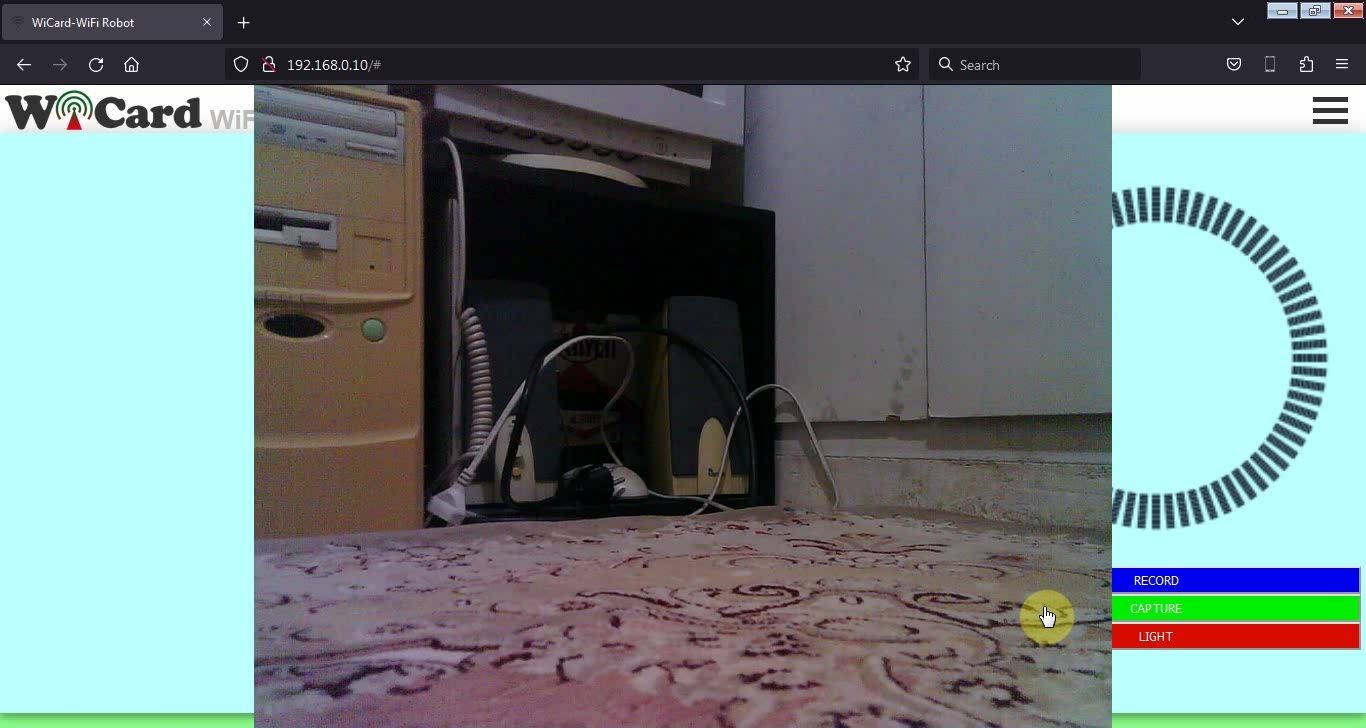
And by tap of clicking again on the image, the stream size will change to the original size.
The quality can be set in the settings page.
- Higher quality has a lower frame-rate.
- If you enlarge the stream, the recording quality will be the same as enlarged stream.
- When the stream is enlarged, the tools don’t work.
- Do not open two pages at the same time. The module can handle only one page at a time.
- The WiFi signal strength takes effect on the module capability and the video streams.
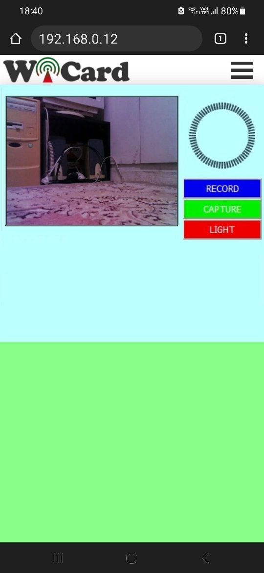
The responsive WebApp
This web application is also compatible with cell phone and mobile device browsers:
The menus
The Web Application is divided to 3 menus. The menus can be selected by click on the menu button.
“Controller” refers to the control tools and the “Online Stream” page, “Memory” refers to the file manager and “Settings” refers to the settings page.
The File Manager
In the “Memory” page, you can see the saved images (.jpg format) and the recorded videos.
The videos save in “.jp4” format and in the current firmware revision, you can either play the .jp4 video file in this page or with the KMPlayer.
Also you can access to another device’s memory in this page with setting the “Target” device in the settings page.
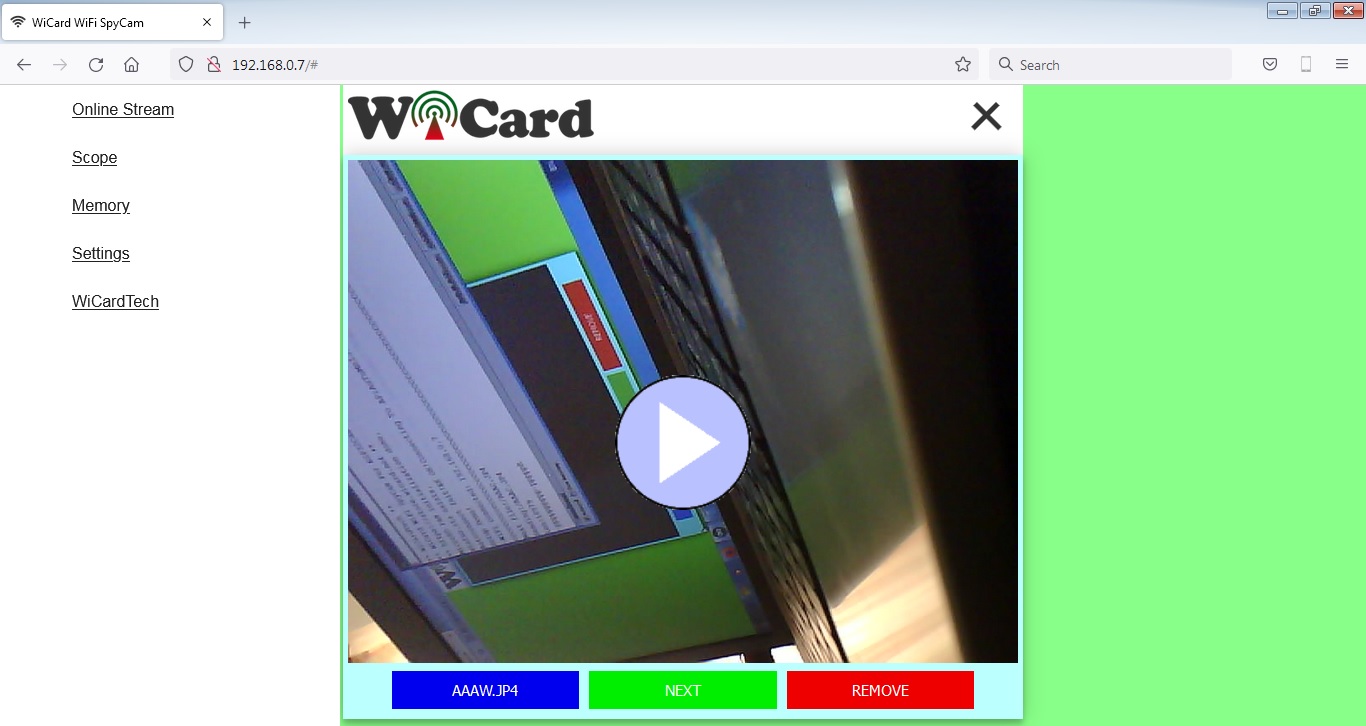
There are 3 buttons under the image:
- File name (direct link) button.
- Next file button
- Remove button
The left button under the image (blue button) shows the file name and has the direct link of file (you can right click on it and copy the link).
The middle button shows the next file.
And the right button, removes the file.
You can download the images by tap or click on the image.
By click on the play button (middle of the JP4 file image), the video will be downloaded and played along with the audio and you can pause the video by tap or click on the image.
- Downloading the videos may take a while, it depends on the video data length and the WiFi signal strength.
The Settings menu
The web application’s settings menu has been divided to 5 parts:
- Modem Configuration
- Device Hotspot Configuration
- Camera Configuration
- Local Network Configuration
- Local Network Map
- You can directly access to the settings menu with http://ip#settings link (e.g. 192.168.4.1#settings).
- With the target feature, you can access to WiFiRobot (rev 1.0) and also both of SpyCams and IPCams (rev 1.3) memories and play the .JP4 and .JP5 videos.
Updating the project
I’m going to update and upgrade this project. I can add “AI” features (yes, “Artificial Intelligence”) or just a few options and bug fixes. Depending on you support 🙂
The project is available in the following:

Written by: M. Mahdi K. Kanan – Full stack electronics and programming engineer and the founder of WiCardTech