Spy Camera (Video, Audio & Network Stream) With ESP32-Cam
This project is an “ESP32 WiFi Camera Microphone (Spy Camera)” firmware arduino source code (.ino) with Chain Network feature which is based on the “ESP32 WebApp Builder” project. The “Chain Network” is a local network which the devices one by one are connected to the each other.
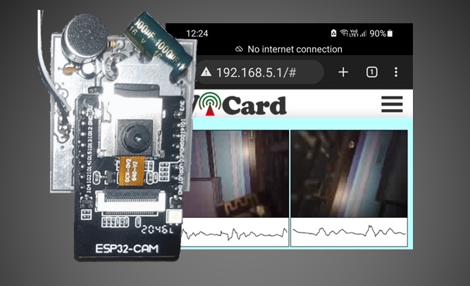
The Spy Camera project uses the “AI Thinker ESP32-CAM” module which has a 2MP Camera, 10 I/O pins, an on-chip LED and one MicroSD slot to store the images and videos. With its tiny sized camera and 240MHz CPU is able to provide a fair quality images and video frames and also a network online stream.
You can either use a “WaveShare Sound Sensor” (or similar) or the suggested circuit as the audio input.
The ADC input (for the audio circuit) is GPIO 33 which is originally connected to the red on-board LED.
This project contains three folders ESP32CamMicProgram (the Arduino source code) and PCB-SCH-BOM.
This project is available in the following link:
SpyCam Project (Video&Audio Recorder) Source Code, PCB and Schematic Plans (ESP32-Cam) – Rev 2.0
Also there’s another project which is only video recorder without the handler circuit:
Arduino ESP32-CAM CCTV, WiFi IP Camera Source Code – Rev 2.0
And the free binary of the firmware of above project (older revision):
Firmware Binary File of Ai Thinker ESP32-CAM CCTV, WiFi IP Camera – Rev 1.1
Uploading the spy camera project
First open one of the files with Arduino program, then set the settings as the following image (Board and Flash Frequency).
- The “Board” must be set on one of the ESP32 Modules before doing anything.
- The start-up CPU speed has been set to 160MHz.
- For the “download mode”, use a jumper for connecting “IO 0” to the GND.
Then turn on the ESP32 module in the “download mode” (GPIO0àGND) and upload the program with using an USB2Serial module.
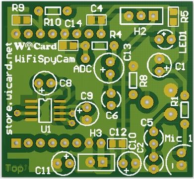
ESP32 Spy Camera PCB
Also there are the PCB files in the PCB-SCH-BOM folder:
This is the assembled circuit with a 5V power source inside of an enclosure: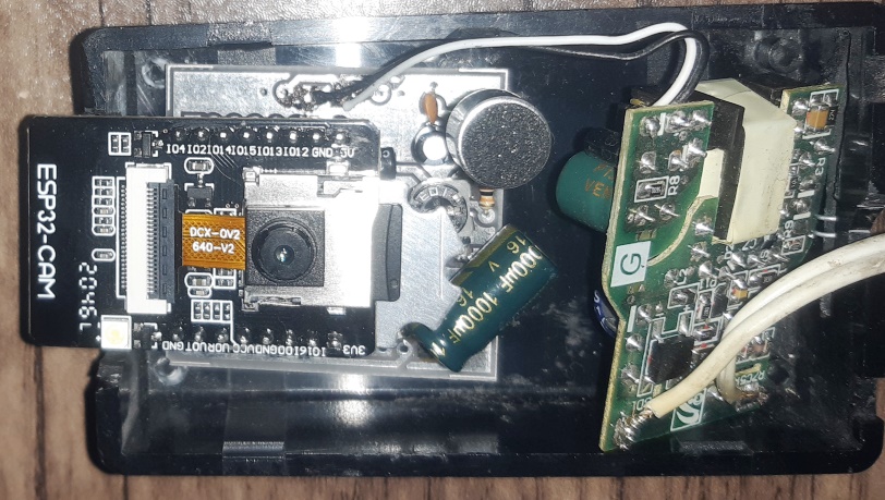
The Chain Network
The “Chain Network” is a local network which the devices one by one are connected to the each other (Series). In the chain network, the first device is the master of network. The starter (either the master or the last joined module) is directly connected to the WebApp. It sends the command to the next device, and the next device sends it to the next one till the last device. The last device response will be sent to the first device and finally the WebApp via the middle devices.
You can join up to 8 camera, either with “ESP32 Spy Camera” firmware (Audio and Video recorder) rev 1.3 or “ESP32 IPCam” firmware (which has not the audio record feature) rev 1.3 in a chain network and see the online stream of the Cameras.
- In the current revision, the online stream is available for only 2 devices in the network, but the file access is available for all of the devices.
The ESP32 Spy Camera Web Application
Plug the power and turn on the circuit and the module in “normal mode”.
Then the LED will blink once (in case of everything is ok). Then you’ll be able to see the module’s hot spot ssid via the WiFi networks in your PC or smart phone.
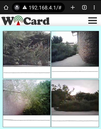
The default SSID is WiCardCamMic and the default password is 12345678. Connect and go to 192.168.4.1 with a PC or smart phone web browser (Chrome or Firefox).
Here’s the web UI:
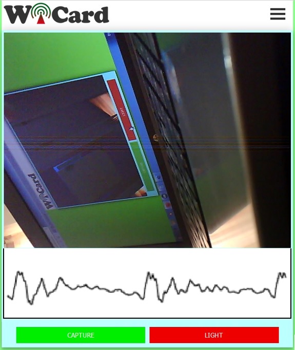
Right after loading the page, the module starts recording and buffering automatically.
Currently the online stream is without audio, but this feature will be added in the future.
By tap on the video image, the image will scale to full with and original size.
There’s an audio signal scope under the screen which shows the received audio signal.
There are two buttons under the scope, with “CAPTURE”, the module will take and save a shot and with tap or click on the “LIGHT” button, the on-chip flash light will turn on and off.
In case of using the “Chain Network” feature, If you join multiple ESP32-Cams to the network, you’ll be able to see an online stream of all of the joined cameras at the same time.
Also you’ll be able to see an online video stream of all of the joined cameras in the “Streams” page:
By one click on each image, the “Capture” and “Light” buttons will appear and by double click on each images, you can enlarge and see the selected camera stream in higher quality.
By tap or click on the “menu button” (top-right), the menu items will be appeared:
- Do not open two pages at the same time. The module can handle only one page at a time.
- The WiFi signal strength takes effect on the module capability and the video streams.
- The ESP32 module is weak and the arduino ESP32 compiler (rev 1.0.6) still needs to be updated, so when the module’s access point (hotspot) is turned off (by connecting the module to a modem and turning the temporary hotspot button on in the settings page), the device has a better performance.
The responsive WebApp
This web application is also compatible with cell phone and mobile device browsers: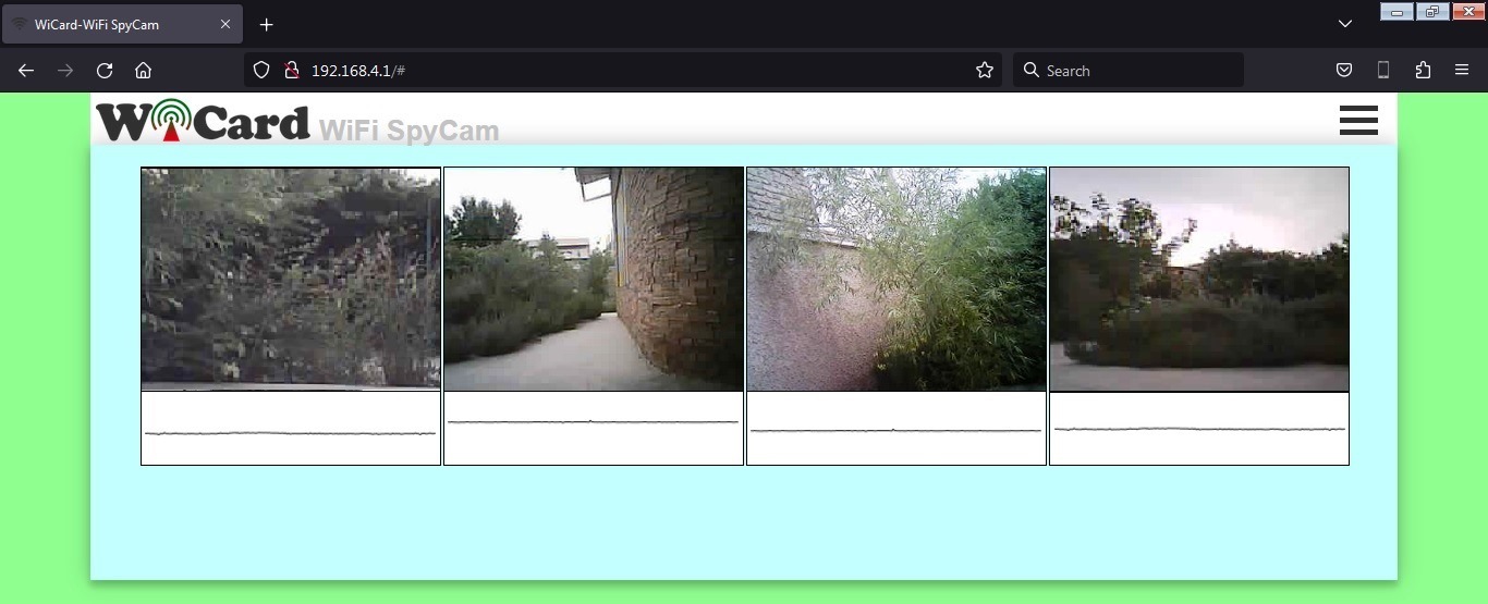
The menus
The Web Application is divided to 3 menus. The menus can be selected by click on the menu button.
“Streams” refers to the “Online Stream” page, “Memory” refers to the file manager and “Settings” refers to the settings page.
The File Manager
In the “Memory” page, you can see the saved images (.jpg format) and the recorded videos.
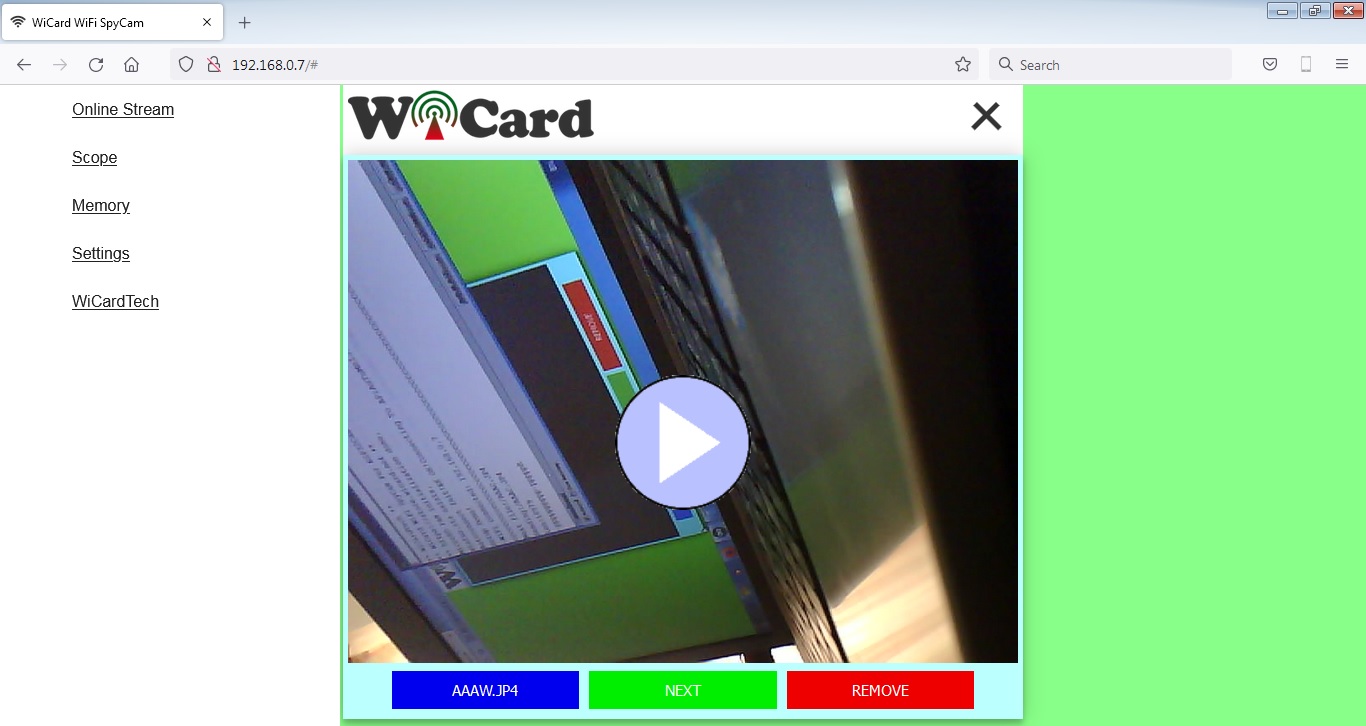
The videos save in “.jp5” format and in the current firmware revision, you can only play the videos in this page.
Also you can access to another device’s memory in this page with setting the “Target” device in the settings page.
There are 3 buttons under the image:
- File name (direct link) button.
- Next file button
- Remove button
The left button under the image (blue button) shows the file name and has the direct link of file (you can right click on it and copy the link).
The middle button shows the next file.
And the right button, removes the file.
You can download the images by tap or click on the image.
By click on the play button (middle of the JP5 file image), the video will be downloaded and played along with the audio and you can pause the video by tap or click on the image.
- Downloading the videos may take a while, it depends on the video data length and the WiFi signal strength.
The Settings menu
The web application’s settings menu has been divided to 5 parts:
- Modem Configuration
In this section you can see the available access points, the connection status, the device MAC address and the DHCP IP.
Also in this section you can set the SSID and password of the modem’s access point.
* If the modem is not available, clear the SSID text box and save it. - Device Hotspot Configuration
In this section you can set your module’s hotspot SSID and password.
The secure link is a string which will be added at the end of your module’s IP address. For example if you set it “123”, the IP address of the WebApp of your module will be 192.168.4.1/123 instead 192.168.4.1
The even means the default IP is 192.168.4.1, the Odd means the default IP is 192.168.5.1
Hidden HotSpot will set the HotSpot hidden.
Temporary HotSpot will disable the HotSpot right after the module is connected to the modem or joined to the network (For the last device in the network).
* The SSID must be without space in case you’re going to join the device to the network.
* You can’t join or link two devices with the same IP or SSID, so use Even-Odd-Even-Odd… IPs.
* The linked device is the device which has been connected to the module’s HotSpot In the network. - Camera Configuration
In this section:
* You can set the device’s network channel. The channel must be a number between 0-7 and the devices can’t have the same channel.
* The “Quality” of online stream and recording which can be Low (320*240), Medium (640*480) or High (800*600).
* The “Record Time” can be 10Sec, 30Sec, 1Min, 2Min or 4Minutes.
* The “Motion Detector Sensitivity” is the internal image processing sensitivity for motion detecting and can be Off, Low, Medium or High.
* The “PIR Input” switch enables and disables reading getting record command from “GPIO 3”.
* The “Flash Light” switch turns on and off the on-chip power LED during the recording.
The internal image processing sensitivity also depends on the scene light and objects. - Local Network Configuration
In this section you can set the “Master” device and also set the userGlobal() function execution delay.
The linked WiCard IP is the IP of linked device to the module’s access point.
If you don’t turn on the “Join Required” switch, the module will be set as Master.
* If you’re not going to use the chain network feature, do not turn on the “Join Required” switch.
* Only one device can be the “Master” in the chain network, which is the first device. So the “Join Required” switch must be turned on in the other devices. - Local Network Map
In this section, the attached devices in the chain network will be shown.
For the master, it starts with master’s SSID, then the second ESP device, until the last one, but for the last device, the sort is vice versa.
With typing the target device SSID in the target text-box, you can access to the target device’s memory.
- With the target feature, you can access to both of IPCams and Spy Camera (rev 1.3) memories and play the .JP4 and .JP5 videos.
- You can directly access to the settings menu with http://ip#settings link (e.g. 192.168.4.1#settings).
Programming Manual
For the programming of the Spy Camera project, use the pre-defined functions in the files which start with “user”.
Add your start-up script to the “userInit()” function in user_init.ino file. No need to do wifi or server configuration. This configuration already have done in the firmware system files (e.g. systemInit() and setup()).
The “userLoop()” function (user_loop.ino) calls repeatedly (like arduino “loop()” function), If your program needs to execute a statement repeatedly (e.g. reading a sensor’s data), insert your script in this function.
The “webapp.h” file is the root page’s script. You can customize sWebApp variable in that file if you’re going to make changes in the Web UI.
Also you can customize the “userGetSettings()” function (user_settings.ino), for adding more settings to the firmware. The WebApp execute this function when you click on the Settings menu.
After you click on the SAVE button of the user-defined settings, the “userSetSettings()” functions will be called.
- The settings will not be shared in the network and each device has its own settings.
The “userMain()” in the “user_main.ino” file, calls once when you click on the “Streams” menu (or initially after loading the root page).
The “userSubInit()” in the “user_sub.ino” file, calls once when you click on the “Memory” menu and sends the available devices in the network back.
- The “networkStarterCheck()” bool functions says whether the module is the network starter or not.
The “userGlobal()” function in the “user_global.ino” is not working in this revision.
In the AC.h file, if you remove “#define LOG_ENABLE”, the logs will not be shown and the log memory would be released. Also removing this line, enables the “GPIO 1” LED feature.
When LED blinks multiple times, that means an error occurred (either memory error or camera error).
During the recording, the “GPIO 1” LED turns on.
- The “GPIO 1” LED is disable when serial log is enable.
In the user_global.h file, you can change the motion detector image processing accurancy with the following “define” variable:
#define CAP_DIFF_ACCURACY 110
In The “espCamReset()” function in user_init.ino file you can change the default image sizes:
/* Size and Quality
FRAMESIZE_96x96, // 96×96
FRAMESIZE_QQVGA, // 160×120
FRAMESIZE_QQVGA2, // 128×160
FRAMESIZE_QCIF, // 176×144
FRAMESIZE_HQVGA, // 240×176
FRAMESIZE_240x240, // 240×240
FRAMESIZE_QVGA, // 320×240
FRAMESIZE_CIF, // 400×296
FRAMESIZE_VGA, // 640×480
FRAMESIZE_SVGA, // 800×600
FRAMESIZE_XGA, // 1024×768
FRAMESIZE_SXGA, // 1280×1024
FRAMESIZE_UXGA, // 1600×1200
FRAMESIZE_QXGA, // 2048*1536*/
if(ucVidQuality == VID_QUALITY_LOW) //Low
{
config.frame_size = FRAMESIZE_QVGA;
config.jpeg_quality = 20; //0-63 lower means higher quality
}
else if(ucVidQuality == VID_QUALITY_MEDIUM) //Medium
{
config.frame_size = FRAMESIZE_VGA;
config.jpeg_quality = 10; //0-63 lower means higher quality
}
else if(ucVidQuality == VID_QUALITY_HIGH) //High
{
config.frame_size = FRAMESIZE_SVGA;
config.jpeg_quality = 5; //0-63 lower means higher quality
}
else //if(ucVidQuality == VID_QUALITY_NET) //Network Stream
{
config.frame_size = FRAMESIZE_QQVGA;
config.jpeg_quality = 20; //0-63 lower means higher quality
}
- The process of smaller images is faster.
- If you have not enough programming and electronics knowledge, do not make changes.
- The size of every packet is limited, so increasing the quality may cause problems in the video recorder and player.
- The WiFi signal strength takes effect on the module capability and the streams.
The Spy Camera project is available in the following:

Written by: M. Mahdi K. Kanan – Full stack electronics and programming engineer and the founder of WiCardTech
2 Responses
Great article,Very helpful and well-written. Thanks
You’re welcome.