Battery Charger Circuit (1.5-24V) With ATmaga8A – Code and Plans
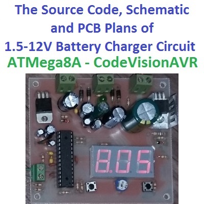
The main processor of the “1.2-24V Battery Charger Circuit” is ATmega8A. ATmega8A is an AVR 8 bit microcontroller which has 28 pins.
This circuit has an internal volt-meter and temperature-meter with digitally calibration feature.
The project contains 3 folders, “CodeVision Source”, “PCB-SCH-BOM” and “sim”.
There’s a source code folder in this project which contains the CodeVision program files (C) and pre-compiled HEX file. To re-compile or check out the source code, open “BatteryCharger.prj” with codeVision AVR software. First of all set the fuse bits.
The microcontroller uses its internal 8MHz oscillator. Also the BOD is enabled to check the voltage if it is not under 2.9v to saving the EEprom data.
Project Compilation
Before compiling the project, go to “headers.h” file and Search for “#define SIM”. In case you are going to test the program with “Proteus Software”, it should not be logged.
But if you’re going to upload the program into the microcontroller, log it with two slashes:
//#define SIM
Then compile the project with ctrl+F9.
- It is recommended to use a supported programmer by the compiler software.
- The fuse high byte is: 0xD9
- The fuse low byte is: 0xB4
The Proteus Simulation File
Also in this project there is a Proteus simulation file inside of “sim” folder. Open it with Proteus Schematic and set the project .COFF file by double click on the microcontroller, then run the simulation.
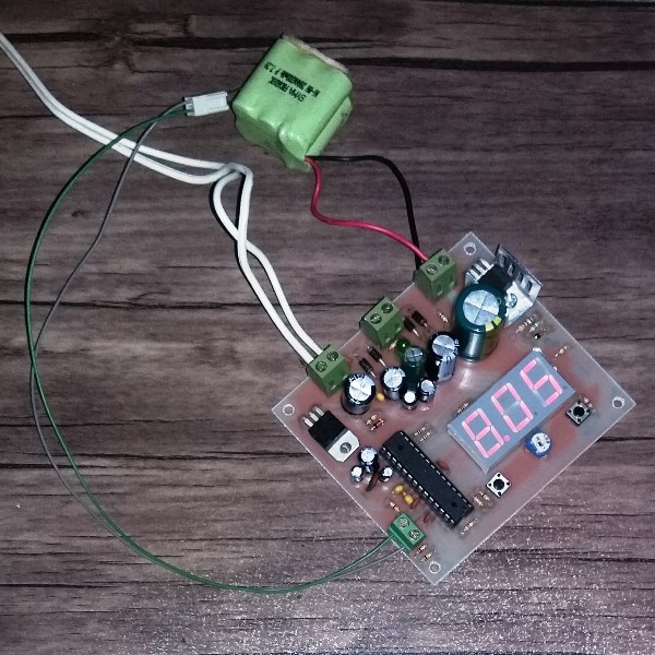
The Battery Charger Circuit and PCB
In the “PCB-SCH-BOM” folder, there are 6 files:
- AutoIrrigation.prjpcb (Altium project)
- AutoIrrigation_PCB.pcbdoc (Altium PCB file)
- AutoIrrigation_SCH.schdoc (Altium schematic file)
- AutoIrrigation_BOM.txt (Bill of materials)
- AutoIrrigation_SCHPDF.pdf
- AutoIrrigation_PCB_DIPTRACE (DipTrace PCB file)
The PCB is 8cm*9cm with 4 3mm pads in the 4 edges of the PCB.
Mountage and assemble the parts according to the bill of materials.
The Con1 connector is AC input which must be under or equal with 24VRMS. And Con2 is the DC input which can be vary between 7V to 27V.
The Con 3 is the charger’s output and must be connected to the battery + and -. And Con4 is the NTC’s input and in case of using the temperature sensing feature, a 10K ohm NCT resistor should be connected to this connector.
- The voltage on Con2 should not exceed 27V.
- Connect all of the + (VCC) and – (GND) correctly.
- In case of your power source has not a fuse, add a fuse before connecting to the battery charger circuit.
- The power source current should not exceed 5A.
- In case of charging with more than 1A current, use a heat sink for the Q2, L1 and L2.
- If the current is more than 2A, use a large-sized heat sink and/or a fan.
- The temperature of Q2, L1 and L2 should not exceed 80C.
- The power source voltage should not be more than 5 volt than the charging voltage.
- Do not use the too sensitive batteries in this circuit.
The 1.2V to 24V Battery Charger Circuit’s Configuration
There are two push buttons (UP and Down) and a potentiometer (P1) for the configuration.
To calibration of the temperature sensor, connect the NTC and then plug the power source. When — is appeared on the segment screen, press UP button.
Then “tpc” will be appeared on the screen and then the temperature value number will blink.
- The accuracy is 1 degree of Celsius. 1.2C means 120 degree of Celsius.
With using a standard temperature meter and a glass of warm/hot water calibrate the circuit’s temperature meter. UP and Down is the “Divider” and potentiometer is the “Subtractor”.
- The calibration takes time and patience.
- When the number stops blinking it means the device is in ready to work state.
- The calibration will be saved when the device enters to the ready to work state.
To calibrating the circuit’s internal volt-meter, connect a battery (or DC power source) to the Con3 and after seeing —, press the Down button.
Then the voltage of the battery appears and blinks. Calibrate the voltage with UP and Down and using a standard volt-meter.
- There’s no need to connect the power source to the Con1 or Con2 during the volt-meter calibration.
To setting the “Charging voltage” and the “Maximum battery voltage”, unplug everything from the circuit first and then wait for at least 1 minute.
Then connect the power source to the Con1 or Con2. When — disappears, the voltage of Con3 appears (without blinking and the voltage should be 0.00).
With pressing the UP button, “chg” will be appeared and you can set the “Charging voltage” with Up and Down buttons.
And with pressing the Down button, “bat” will be appeared and you can set the “Maximum battery voltage”.
- The charging voltage must be more than the battery voltage.
The Battery Charging
After the configuration, connect the battery to the Con3. The battery’s voltage will be appeared after —. And then the power source to the Con1 or Con2.
The voltage of a proper battery with the correct configuration will slowly increase.
Press the UP button to see the percent and the temperature.
Press the Down button to pause the charging process.
When the battery is fully charged, the right “Dot” on the screen will be turned on.
- The minimum battery voltage is set on 0.5V and a proper battery’s minimum voltage is half of its maximum fully charged voltage.
- When the battery is fully charged, it may decrease its voltage a little bit, after a few seconds. It is normal.
- It’s recommended to wait for a few minutes after the battery is fully charged and then unplug it;
- If the battery’s temperature increases so much, connect the temperature sensor, which disconnects the charger if the temperature is more than 50C and reconnects on 40C.
- Blinking “OH” on the screen means the over heat.
The project is available in the following:

Written by: M. Mahdi K. Kanan – Full stack electronics and programming engineer and the founder of WiCardTech