Diode and its types – diode usage in the circuit
Diode is another electronic component that has two pins. These two pins (bases/legs) are called cathode (negative) and anode (positive). The cathode pin is usually shorter or closer to the white (or black) ring on the body of the diode.
The diode is shown on the schematics map with the D letter, and its applications in electronic circuits include rectification, illumination, voltage regulation, optical sensors. Its types are: rectifier diodes, Light-emitting and light-sensitive, zener, detector, varicap, tunnel, etc. which we are dealing with three commonly used types here.
Due to the materials used in diodes, the current passes through them only in one direction, from Anode to the Cathode.
In these parts, two silicon or germanium elements (semiconductor or semiconductor elements) are used, which are combined with other materials and create P (positive) and N (negative) pieces.
These two pieces, if used alone, are able to pass current easily, but if the atoms of these two pieces get so close together, the current only goes from P to N.
If we want to know how the diode works, we have to deal with a complex issues of quantum physics. So, for now, accept the diode as it is.
- The connection of the diode pins in the form of P to N is called direct bias (or forward voltage) and the opposite connection of this state (N to P) is called reverse bias.The diode bridge separates the positive and negative half waves of each output from each other and combines the positive and negative ones separately.
Rectifier diodes and how to use them in the circuit
Rectifier diodes pass the current only in direct bias mode (From P to N).
The figure below shows the appearance of these diodes and their schematic symbol and the direction of the current:
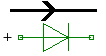

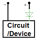
These diodes can be used in the current input, so that when the positive and negative of the circuit are wrongly connected, no current enters the circuit.
The figure below shows how to connect this diode as a protector diode for the circuit:
You can also use this interesting feature of the rectifier diodes in the voltage adapters.
A voltage adapter is a device that converts AC current into DC.
The method of using the diode in the adapter depends on the type of transformer.
If the transformer had 3 outputs, we should use the diodes as follows:
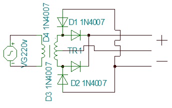
In the circuit shown above, alternating current AC exits from the top and bottom paths of the transformer output.
These two outputs have a phase difference of 180 degrees, that is, if the upper one is positive and at its highest voltage (relative to the middle output), the lower one is negative and at its lowest voltage (relative to the middle output).
Upper output:
Lower output:
Now, by using a diode, we send negatives to one wire and positives to another wire.
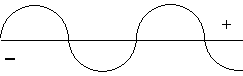
What happens is that in the upper wire (+) the current is as shown below (relative to the middle wire):
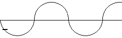
and in the lower wire (-) the current is as shown below (relative to the middle wire):
Alternating currents usually have a constant frequency. For example, in the case of city electricity, it is 50Hz.
This means that the voltage in the city electricity phase wire (L / Live) changes 50 times from -320 to +320 and from +320 again to -320 V, in a period of 1 second, relative to the neutral wire (N / Null).
But the average absolute voltage is 220 volts (rms voltage).
These changes in high voltages and current are very dangerous and direct contact can cause serious injury or death.
If the alternating supply voltage is 220 volts and the ratio of the transformer is about 0.110, then the voltage difference in the upper wire with the middle one varies between 0 volts and about 12 volts, and the lower voltage with the middle one varies between 0 volts and -12 volts.
The average voltage between the upper wire and the lower one will be 24v (220*0.11). The following figure captured by a simulator and considering the internal resistances:
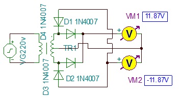
- In this type of the transformers, the middle wire always has a voltage of 0 volt.
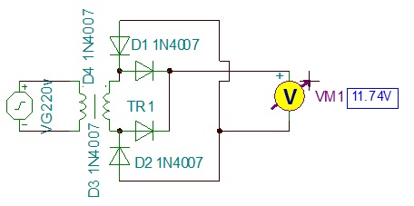
If the transformer has 2 outputs, we must connect the diodes in the bridge method
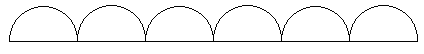
The diode bridge separates the positive and negative half waves of each output from each other and combines the positive and negative ones separately.
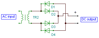
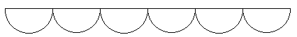
Here we have only separated the positive and negative and there is no 0v anymore, that is, the upper voltage is +6 volts and the lower voltage is -6, the difference between the two is 12v. The following figure captured by a simulator and considering the internal resistances:
- To remove the half waves and noises, you need a capacitor; In the capacitor section, we will discuss how to use the capacitor to remove the noises and build a direct line voltage and current.
To use this type of diode, we need to know a few things:
- The minimum required current (IS) required for the current to flow.
- The maximum tolerable current of the diode (IBV) which, if exceeds, will damage the diode.
- The minimum input voltage (VJ) required for current to enter.
- The maximum tolerable voltage of the diode (BV) which if exceeds, the diode will be damaged.
- Diode resistance (RS) which is required for more accurate calculation.
To buy a diode from the market, you need a datasheet file of the desired diode, which contains the specifications of the diode standards.
You can search for the datasheet file in Google.
In the table below, the characteristics of some examples of widely used standards of rectifier diodes are mentioned:
| RS (Ω) | BV (v) | VJ (v) | IBV (A) | IS (A) | Type |
| 2 m | 50 | 550 m | 5 m | 36 n | 1N1183 |
| 2 m | 600 | 550 m | 5 m | 36 n | 1N1190 |
| 2 m | 50 | 550 m | 3 m | 36 n | 1N1199 |
| 2 m | 100 | 550 m | 2.5 m | 36 n | 1N1200 |
| 43.2 m | 50 | 300 m | 1.2 | 403 n | 1N4001 |
| 8.1 m | 50 | 550 m | 3 | 500 n | 1N5400 |
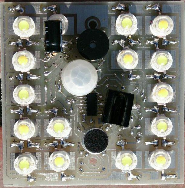
Optical and infrared diodes and how to use them in the circuit
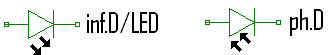
In the common light-emitting diodes (LED), the resulting light can be seen by the eyes, but in infrared diodes (inf.D), the resulting rays (infrared rays) cannot be seen (these rays can be detected by a camera). With the help of photo-diodes (ph.D), you can receive the energy (rays) from them.
Light diodes have 2 pins or bases, one pin which is taller and is connected to the current input (positive) is called anode and the other pin which is usually shorter and is connected to the current output (negative) is called cathode.
The images below shows the appearance that these diodes and their schema on the maps:

Some light emitting diodes are two colored and have 3 pins; One pin is common and the other two pins are for each color. If both colors light up together, another color is made from the combination of them.
Light-emitting diodes can usually withstand an average current of 10 milli-amps and a voltage between 3 and 5 volts.
These diodes in reverse bias do not pass if the voltage is low, otherwise will damage.
If they burn, they may pass very little current and no longer produce light.
Infrared transmitter and receiver diodes have many uses, for example, you can use them to determine distance, color recognition, sending information, anti-burglary alarms, etc.
The transmitted frequency and information can be entered into the infrared diode with the help of a timer IC and received by the photo-diode and accepted or rejected by an operational amplifier IC.
Seven Segment LEDs (7 segment)
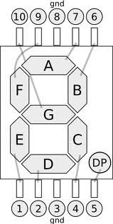
The seven segment LEDs consists of 7 or 8 light-emitting diodes, packaged in the form of the number 8 or 8. (the number 8 and a dot/point in its right).
These LED packages have one or two anode pins (common anode) or one or two cathode pins (common cathode), and the rest of the pins are each related to turning on one of the LEDs in the package.
The following picture shows an example of these packages (common cathode):
Zener diode and how to use them in the circuit
These types of diodes are like a resistor that changes its resistance when the voltage changes; That is, their P and N are made in such a way that if the voltage difference between the two ends of the diode exceeds a limit in the opposite bias, it will pass the over-voltage relative to that limit.
This action causes the excess voltage to disappear.
This property can be used to keep the voltage constant.
To use zener, it is better to use a load resistor.
Zener schema on the plan:

Load resistor: A resistor that is connected in series before the zener in the circuit to prevent the zener from being damaged.
The method to place the zener and load resistance along with the consumer/circuit and the power supply is as the following:
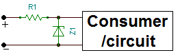
In the picture above, Z1 is the zener diode and R1 is the load resistor.
The following example shows how to calculate the Zener diode and the load resistor:
We have a 10v power supply which its tolerance is 10%, and its ripple voltage is one volt, we can have an 8v voltage (10v-10%-1v ripple) with a low ripple voltage with the help of a zener.
To use the zener, we must know the following:
- Power supply ripple voltage
- The amount of voltage required by the consumer (this voltage should be at least v1 lower than the lowest main voltage of the power supply.)
- Consumer current rate
- The amount of Zener power (obtained during calculations) and the maximum Zener voltage
- Power and load resistance value (which is obtained during calculations.)
The ripple voltage of the power supply is usually written on it, the amount of consumer voltage is also written on it if it is pre-made, and if you made it yourself, you can calculate it using the mentioned formulas in the tutorials.
The amount of consumer current can be obtained through calculation or by a multi-meter.
The maximum voltage of the zener is also equal to the voltage required by the consumer and the power of the zener is obtained through the following equation:
P=I×V
In the above relationship, P is the zener power, V is [the power supply voltage – consumer needed voltage], and I is the consumer current between the V, which is calculated by the ohm’s law and the load resistor value.
So you will need a zener with V voltage and P power.
The value of load resistor is also obtained through the following equation:
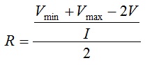
In the above relationship, I means the current required by the consumer, Vmax means the maximum power supply voltage and Vmin means the minimum power supply voltage.
The load resistor power is also obtained through the following equation:
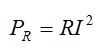
In the above relation, I is the current of the consumer.
- Use the zener with higher power than the calculated power.
Diode applications examples
OR gate:
Necessary equipment: 2 diodes 1N400x (rectifier), 2 resistors, power supply.
In order to be able to implement what we have in mind on the circuit, we need to define the logic of “and”, “or” and “opposite” for the electric currents.
The logic for electric currents is defined by special parts which are called logic gates.
This circuit defines the “or” for the circuit; In such a way that the current of I3 is drained or cutted according to I1 and I2.
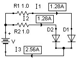
The truth table is in the below:
| I1 | 0 | 0 | 1 | 1 |
| I2 | 0 | 1 | 0 | 1 |
| I3 | 0 | 1 | 1 | 1 |
Circuit analysis: the current enters from the positive pole to the circuit and after passing through the resistors, it enters the diodes.
Due to the properties of diodes, no more current enters from the output of the gate, and in other words, we have blocked the current here. As can be seen from the above schematic, the output current is the sum of the input currents after the resistors.
If we remove one of the resistors, still the other input supplies the output current.
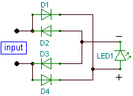
Positive and negative separator:
This circuit is used when positive and negative of the direct current is not recognizable:

Written by: M. Mahdi K. Kanan – Full stack electronics and programming engineer and the founder of WiCardTech