PWM Amplifier With 3 Channels – Active LOW Input and Outputs
This PWM Amplifier has 3 sensitive inputs and 3 outputs with 5A max drain capacity for each channel.
The active state for input and output is “Low” or 0 Volt (Ground) and is suitable for 10 KHz square signal max with 0-100 percent duty cycle and 5-12 volt.
Free download link: 3 Channels PWM Circuit, Suitable for RGB and Motor Drivers
The PWM amplifier is an interface between the PWM source and consumer.
PWM signal is a square signal which is generated by a microcontroller or any other electronical circuit.
The duty cycle is the relative between active state and inactive state time in every pulse.
One of the most features of PWM is controlling motor speed and light dims.
Usually the PWM generators have a low output capacity. For example a microcontroller can only drain 20mA max. If a consumer with low resistance connects to the microcontroller pin, it may damage the chip.
So for the consumers with more than 20mA, a PWM amplifier interface must be used.
This project contains:
- “Altium Designer” PCB file
- “Altium Designer” Schematic file
- “DipTrace” PCB file
- PDF Schematic and PCB
- BOM
PWM Amplifier Circuit Specifications
The amplifier circuit of this project, according to the parts, needs 3-6 mA input and is able to drain 5A.
The active state is “LOW”, for example if the consumer is a power LED, the positive pin (Anode) must be connected to the + of the power source, and the negative pin (Cathode) must be connected to the amplifier output.
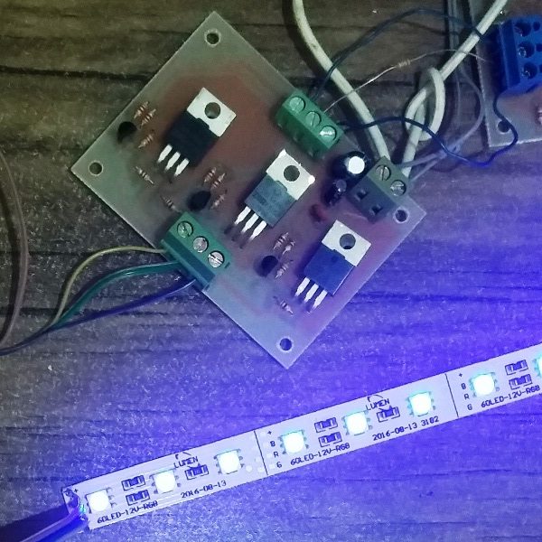
Con1 is the inputs connector, Con2 is the outputs connector and Con3 is the amplifier’s power connector.
The standard working voltage is between 5 to 12 volt, but the parts are able to support 16 volt.
The output has 3 separate channels and is useful for 3 phase motor driver, RGB LED driver, DC motor speed control, robots and etc.
This circuit is also compatible with “Arduino UNO” or other 5V boards/MCUs but the power source of amplifier must be 5V and the power source of consumer can be vary between 5-12V.
- Use heatsink in case of using a consumer which is on for a long time and consumes much ampere.
- To setting analogWrite function For “Arduino UNO” boards, 1024 means off and 0 means 100% duty cycle.
- Use a suitable wire for the ground, according to the total ampere consumption.
- There’s no need to C3 if the amplifier and consumer do not use the same power source.
- To decrease the MOSFETs ampere leakage, use 1K ohm 0.25w resistor instead of 2.2K for R10, R11 and R12.
Converting to input active high, output active low
For converting the circuit to this mode:
- Remove R1 to R6
- Remove T1, T2 and T3
- Connect the center pin of the T1 footprint, to the upper pin of R4 with a 10 Ohm resistor
- Connect the center pin of the T2 footprint, to the upper pin of R5 with a 10 Ohm resistor
- And connect the center pin of the T3 footprint, to the upper pin of R6 with a 10 Ohm resistor
- In this mode, to setting analogWrite function For “Arduino UNO” boards, 0 means off and 1024 means 100% duty cycle.
There’s no need to connect the amplifier’s VCC (+ of the power source Con3 connector) in this mode.
The project is available in the following:

Written by: M. Mahdi K. Kanan – Full stack electronics and programming engineer and the founder of WiCardTech