WiFi ECG Monitor (Oximerer and Heart-Rate Diagram) with ESP8266 and ESP32
WiFi ECG Monitor calculate and shows the blood’s oxygen saturation and the heartbeat-rate with the diagram.
“ESP8266” is a programmable WiFi module which is the main processor of the project and communicates with the oximeter module via I2C and the user interface via WiFi.
“MAX30100 Pulse Oximeter” is a module with two RED and Infrared LEDs and reads the reflection value of the LED’s from top of the finger.
The output data form MAX30100 is so many samples in a second which contains LEDs reflection ADC value.
This project (ESP8266 WiFi Oximeter and ESP32 WiFi Oximeter) contains 8 files:
1- ESP8266WiFiOximeter.ino – the main program
2- I2C.ino (I2C comminucation handler)
3- I2C.h (I2C comminucaton headerfile)
4- MAX30100.ino (The oximeter module handler)
5- MAX30100.h (The oximeter module headerfile)
6- AC.ino (Autoconnect handler)
7- AC.h (Autoconnect headerfile)
8- Monitoring Page (UI file)
First open one of the files with Arduino program, then set the board on “Generic ESP8266 Module” (Tools>board).
Then put the ESP8266 module on the “download mode” and upload the program.
After upload, run the program in “normal mode”.
Then in case you are using ESP12, the blue LED on the board would be turned on for 1 second then turns off. Then you’ll be able to see the module’s hot spot ssid via the WiFi networks in your PC or smart phone.
The default SSID is WiCardCO and the default password is 12345678. Connect and go to 192.168.4.1/config with a web browser.
The WiFi autoconnect configuration page:
In the “Modem Configuration” section, you’re able to view/edit the SSID and password of WiFi modem/router and then click on “Save” after inserting. The module would connect to the modem after about 30 seconds in case of validity of ssid and password.
• This page is also available via the DHCP IP of the module.
In the “Device Hot Spot Configuration“ section, you can set the module hotspot’s SSID and password. Also you can set a password for the internal page with Secure Link section. (Example: the secure link is ABCD and the root page would be at 192.168.4.1/ABCD/ address)
The “Hidden HotSpot” button will set the module’s hot spot as hidden hotspot and the “Disable HotSpot when is connected to the modem” would disable the module’s hotspot, when is connected to the modem.
WiFi ECG Monitor Page
This page is in the root address, 192.168.4.1 (or the router’s given address):
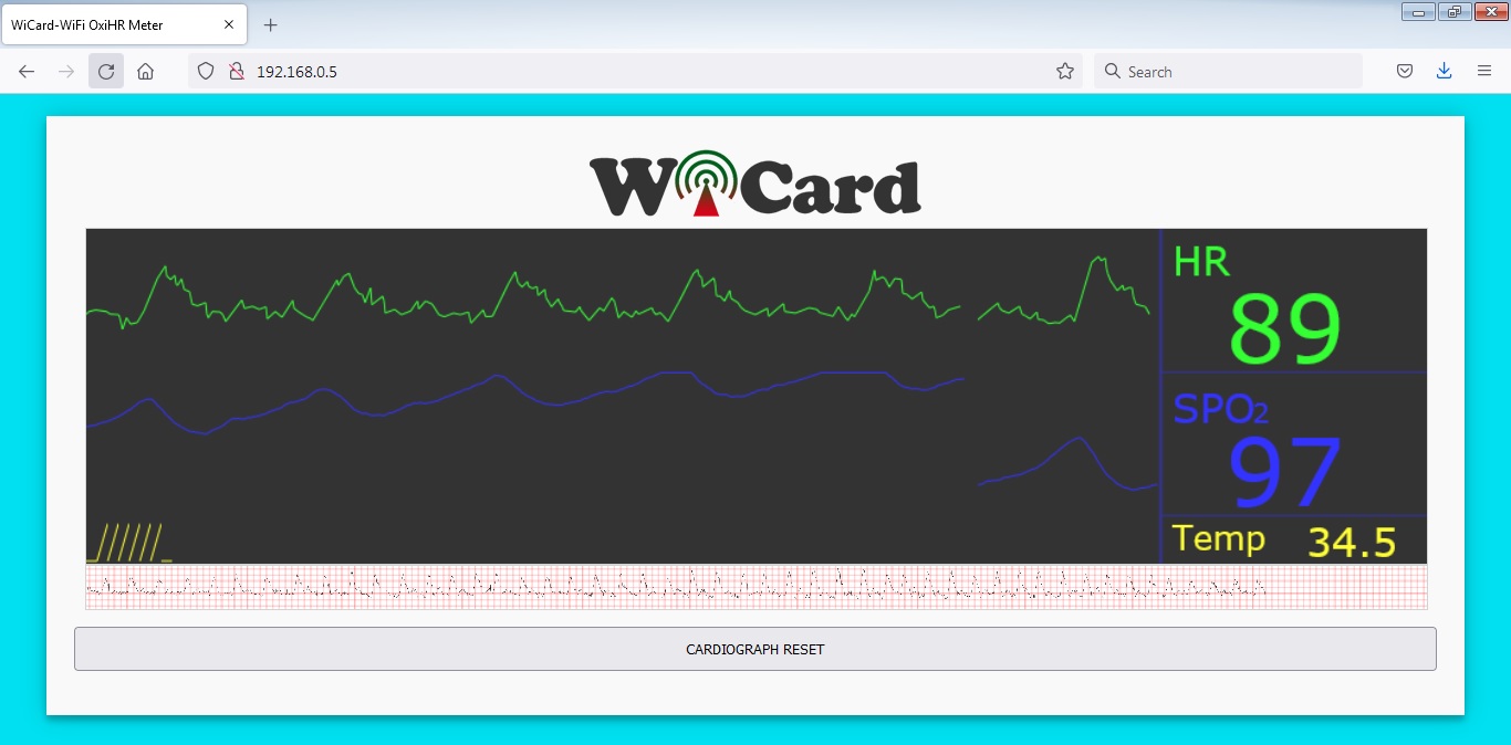
As you can see, the screen will show the heartbeat-rate (HR) and the oxygen saturation percent (SPO2) value with the diagram after about 4 seconds.
The value will be updated every 4 seconds.
The “Temp” section shows the temperature of the top of the finger and when the temperature is between 32 and 35, the values are more accurate.
The diagram above of the “CARDIOGRAPH RESET” button is the cardiograph history during about 40 seconds. Save it by right click on it and click on “Save Image As”.
The “CARDIOGRAPH RESET” button, resets the cardiograph history.
• Try to wrap something around your finger and the MAX30100 module, because this module is very sensitive on the peripheral lights.
• This is not a medical project even if the value be accurate. Please do not use for the patients.
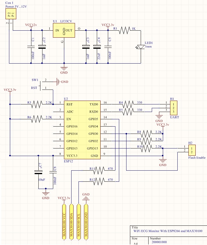
The ECG Monitor’s Schematic
Here’s the tested schematic which uses only 4 wires for the module.
Errors in Logs
Open arduino “serial monitor” when the system is connected to the USB. If you receive I2C error, that means the wiring/connection is not correct.
If you received “e2” error, that means finger is not on the MAX30100 sensor.
It is normal to receive “e3” rarely, but if the error is too much, that mean the finger is not completely on the sensor or the module is receiving peripheral lights.
Programming and Regulation
In the AC.h file, if you remove “#define LOG_ENABLE”, the logs will not be shown and the log memory would be released.
The “LOOP_10_S” value set the printing “-” In the log time. The best time is 10 seconds and set according to your module CPU frequency.
In the MAX30100.h file, if you “unlog” this parameter: #define MAX30100_TEST_MODE, the device will turn on in test mode, which shows IR and Red LED values only in the serial monitor. These two values should be close to each other (less than 3000 unit difference).
By changing the LED power in the following line, the values will change:
#define LED_CONFIG_VAL RED_LED_11_MA|IR_LED_33_MA
These two lines has been used for the oximeter and heartbeat-rate diagram regulation:
#define OXIMETER_REGULATED_VALUE 115 //between 110-120
#define HEART_RATE_GRAPH_REGULATION 1 //1 or 2
Only make change to the regulation values if you have a standard pulse oximeter and comparison of the output value is not the same and the pulse oximeter. If you have not enough programming and electronics knowledge, do not make changes.
• The WiFi signal strength takes effect on the module capability and the ECG streams.
• It’s pretty important that how the finger is placed on the MAX30100 Sensor’s eye to receive correct and accurate values.
The projects are available in the following:

Written by: M. Mahdi K. Kanan – Full stack electronics and programming engineer and the founder of WiCardTech
One Response
Greetings! Very helpful advice within this post! It’s the little changes which will make the largest
changes. Many thanks for sharing!