Electronic Parts
All parts that have conductive ends/bases/pins and make changes on the input electric current, are called electronic parts.
You see many electronic components every day and now you have decided to learn how to work with them. If you have more advanced parts, it means that you have access to higher technology.
If you have plan to build your own circuit, it might be better to learn to work with the existing parts and use them first, and then deal with the internal structure of the part.
Anyway, the internal structure of the parts and how they work may not be very important for learning how to use them, but how they work under different conditions is very important.
Electronic components include resistors, capacitors, diodes, transistors, inductors, relays, transformers, ICs, etc., and each of them implements a physical formula or a logic or digital algorithm on the currents.
The Resistors, the most widely used electronic parts
Resistor is used to prevent excess current or voltage to other parts. This part is one of the most used electronic parts.
Capacitors
The capacitor is used in digital circuits to remove signal noise and in analog circuits to make signals.
Diode
A diode only allows current to drain in one direction. One of their simplest uses is to protect the circuit when the positive and negative poles of the power supply are connected incorrectly.
Transistor
A transistor is a part that has three pins. Two pins pass the current like a diode only on one side, but according to the current of the third pin.
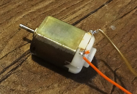
Coil (Inductor)
If we wrap a wire around an iron nail, and connect the two ends of the wire to a battery, the nail is affected by the magnetic field created by the electric current on the wire and becomes magnetized.
The construction of the coil (inductor) is also the same.
The inductor usually consists of two parts, an iron (or air) core and a copper (or other conductors) wire wrapped around the core.
Inductors can also be with ferrite core.
When the current enters to the wire, part of the energy is spent on creating a magnetic field and regularizing the magnetic dipoles in the core, which causes the resistance of the inductor to rise and less current to flow out of it, but after the core dipoles are regularized , the resistance of the inductor decreases. This time, depending on the type of inductor, can be less than a thousandth of a second.
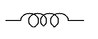
The figure below shows the schematic of the inductor:
Transformer
A transformer can be made by using two inductors. A transformer is a device that can be used to change the input (AC) voltage and increase or decrease it.
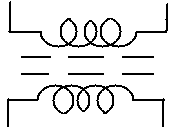
The working method is that by using the magnetic field of one inductor, electric potential is induced in the other inductor.
The transformer has types of step-down (to reduce the input voltage), step-up (to increase the input voltage) and isolation-types which doesn’t make change in the input voltage.
Relay
Relays have different types, but the most common is a part that has 4 or 5 pins and inside it there is a coil (as an electric magnet) and an iron piece with a copper plate on it, and its work is to switch on and off a current automatically (just by connecting the copper plate from one pin to another pin).
The working principle of the relay is that the electric current enters the coil and the coil acts like a magnet and pulls the iron piece attached to the copper plate to itself; In this case, the relay is separated from the upper contact and connected to the lower contact.
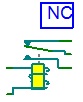
Two pins of the relay are as the input current of the coil (electromagnet). A pin, which is usually located between the two pins of the current detector, acts as a switch head (input). The other two (or one) pins are used as the other end of the switch (outputs) and are marked as NO and NC on the relay enclosure.
When the relay is off, NO (normally open) is open and the other is closed, and when the relay is on, NO is closed and NC is open. The picture below is one of the schematics of the relays, which roughly shows how the relay works:
Relay features and application
This part has many applications in the circuit, for example, when the circuit we made is powered by 5 volts and we want to turn on a 220 volt lamp with the circuit we made, we must use a relay as the 220v switch in the circuit.
In the circuit below, the isolated 220V lamp is connected to the 220V power supply and turns on by the 5V power supply with using a relay:
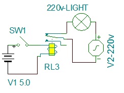
The voltage required for the coil of this relay in the must be 5 volts and its connections should have the capacity to pass 220 volts and the current of the lamp.
The transformers can only be used to make changes in alternating current.
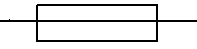
Fuse, the protector of electronic parts
It is a part that is used to prevent the entrance of currents higher than the permissible or authorized limit, for example, if a fuse has a capacity of 5 amps, it will be cut off with a current of more than 5 amps (for example, 5.1 amps). By using a fuse, you can almost protect the circuit from burning out due to too high current input.
Integrated Circuits (IC), the most useful electronic parts
ICs or integrated circuits are a type of electronic components that includes several simple components or circuits that are used in electronics, inside one component.
ICs have at least 3 pins.
By using ICs in the circuit, we can make circuits with very small volume and low power consumption at a very high process speed.

Written by: M. Mahdi K. Kanan – Full stack electronics and programming engineer and the founder of WiCardTech