Automatic Irrigation Circuit with ATTiny13A (PCB, Schematic, BOM)

ATTiny13A is a low-cost and tiny AVR microcontroller with 1KB memory. The PCB file of auto irrigation system has been made by “Altium”, also there is a “PDF” and “DipTrace” revision of the schematic and PCB in the project files.
Auto Irrigation system has a day counter for the time interval between the watering. The default setting is 1-Day interval. That means the system triggers the valve relay every day.
Also there’s a potentiometer in the circuit to set the watering timer between 1 to 30 minutes.
This project contains two folders, “PCB-SCH-BOM” and CodeVision Source.
In the source code folder there is a pre-compiled file in the “HEX” folder. To re-compile or check the source code, open “AutoIrrigation.prj” with codeVision AVR software.
Here’s the fuse setting:
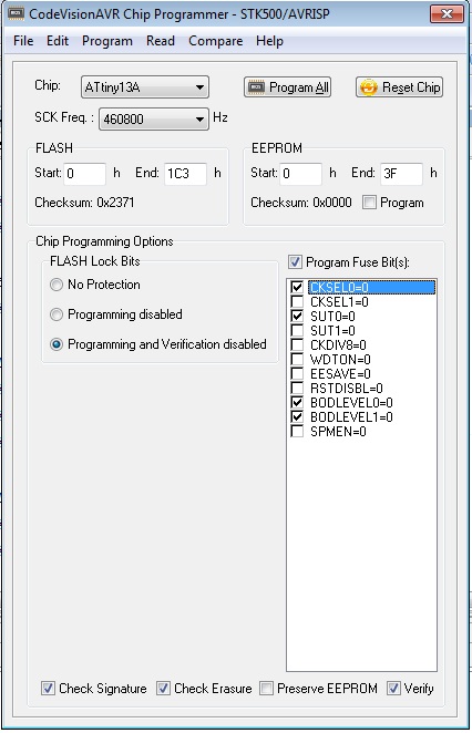
The microcontroller uses its internal 9.6MHz oscillator. Also the BOD is enabled to check the voltage if it is not under 4.5v.
- The fuse high byte is 0xF9 and the low byte is 0x7A.
In the “PCB-SCH-BOM” folder, there are 6 files:
- AutoIrrigation.prjpcb (Altium project)
- AutoIrrigation_PCB.pcbdoc (Altium PCB file)
- AutoIrrigation_SCH.schdoc (Altium schematic file)
- AutoIrrigation_BOM.txt (Bill of materials)
- AutoIrrigation_SCHPDF.pdf
- AutoIrrigation_PCB_DIPTRACE (DipTrace PCB file)
The PCB original size is 50mm*50mm with 4 spacer pads in the edges. You can make your custom changes in the files and then fabricate the PCBs.
Mountage and assemble the parts according to the bill of materials.
- Use the similar parts if some parts were not available.
There is a push button in the circuit to set the schedule (days interval) and also to reset the schedule.
The data and time store in the EEProm memory (Almost every 10 min). Whenever you reset or set the day interval, the watering would be started and the next time would be next days at the same hour.
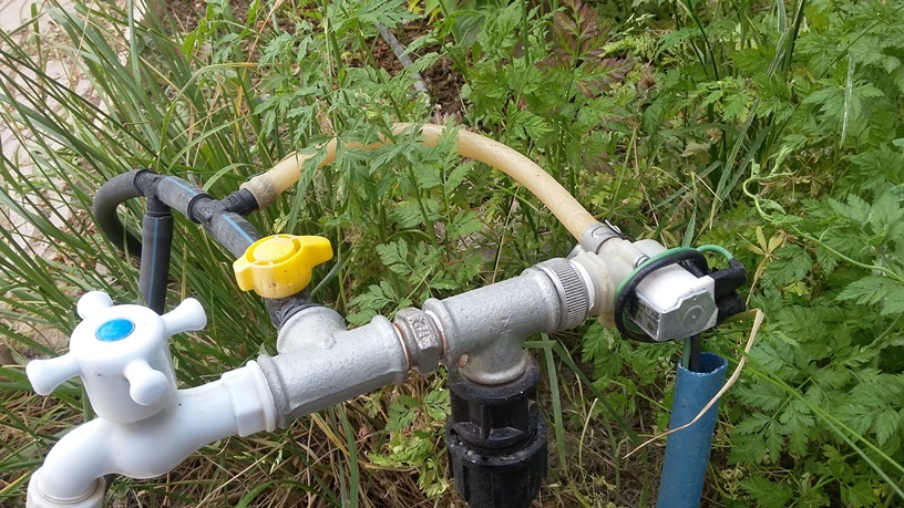
The Auto Irrigation Piping
The suggested piping is using “drop irrigation” piping system. Also use a “220V Water Inlet Valve” or a “5V Solenoid Valve” or etc.
Place a “Drop Valve” beside of every tree or plant and adjust the valve.
Plant the sensor (in case of using) in the driest place. The sensor which is tested with this circuit is “Soil Moisture MH-Sensor-Series Flying-Fish”
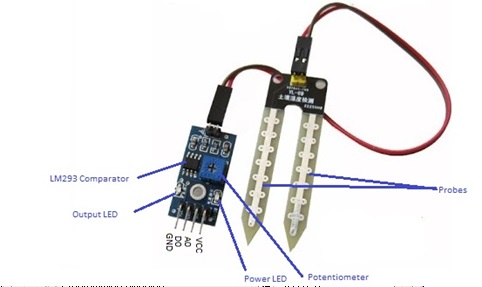
It has a potentiometer to set the required “moisture”. Connect the VCC, GND and “DO” pin to the sensor input (5V, G, S).
The chip check the sensor input every one hour and when the moisture is too low (the output will be low), turns on the valve relay until the sensor input toggles to high or (the watering time ran out).
Setting the auto irrigation
When you plug the circuit to the 5V power source, all of the LEDs will be turned on. The LED3 is always on and shows the power is in the circuit. LED2 turns off and LED1 blinks and shows the interval days in the schedule (the number of blinking).
Then LED1 turns off, and LED2 blinks and shows the number of minutes which the valve switch relay is active.
If you hold the button for 4 seconds during the power on, the schedule will be re-started (LED1 turns off and LED2 remains on for 5 seconds).
If you hold the button for more than 8 seconds during the power on, LED1 will blink and indicates the number of days is interval is increasing. For example release the button after 2 blink in case of setting 2 days for the time interval.
The project is available in the following:

Written by: M. Mahdi K. Kanan – Full stack electronics and programming engineer and the founder of WiCardTech