How To Make A WiFi Controllable Robot
In this article I want to introduce This project is an “ESP32-Cam WiFi Controllable Robot” arduino project.
For making this robot my target was using of everything that I had so I’ve used some old parts and discarded stuff.
The First Step, Finding suitable parts
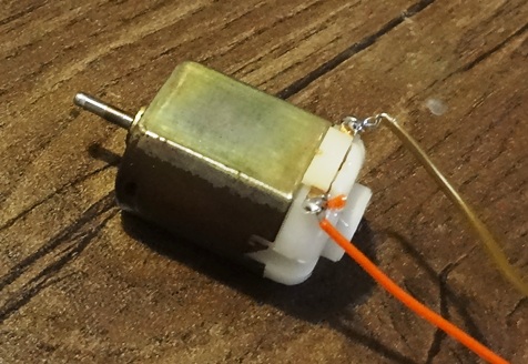
I had two old brushed DC motors with gearbox. I opened their cases and cleaned out their rotors and brushes to get more power from those old motors.
I’ve also used the wheels of a toy car.
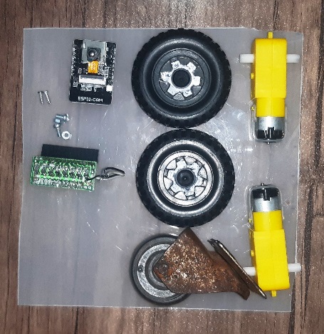
You can use a “caster wheel” as the front wheel (or the rear middle wheel).
The most important part is the ESP32-Cam and ATMega8a as the driver controller.
The other thing that I needed was a “MOSFET” driver board which I already made for a smart house device a long time ago.
Also some “relays”, a voltage regulator and cables.
The Schematics Of WiFi Controllable Robot
Here’s the schematic plan of the circuit of what I’ve made:
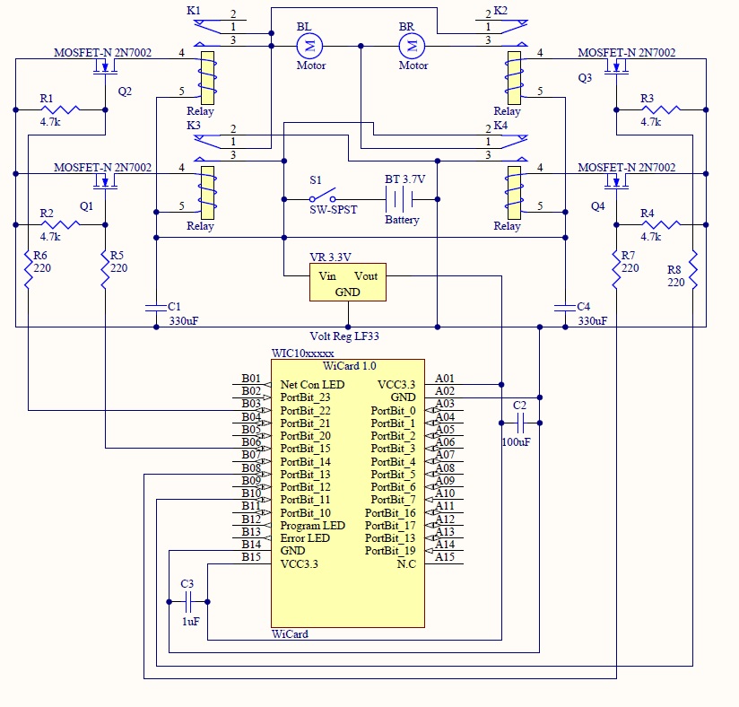
The schematics is so simple because of using ESP32-Cam as its controller. There are four MOSFETs which are driving by the ATmega8a. Also there are four relays, one for the left motor, one for the right motor and two for reversing the battery polarities.
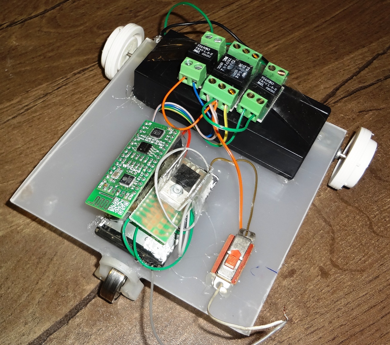
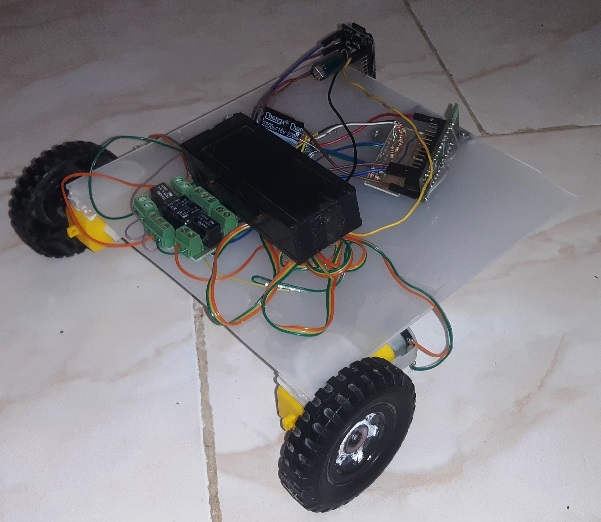
The Robot
This is what I have made:
The Control Box
The next step is uploading the arduino firmware.
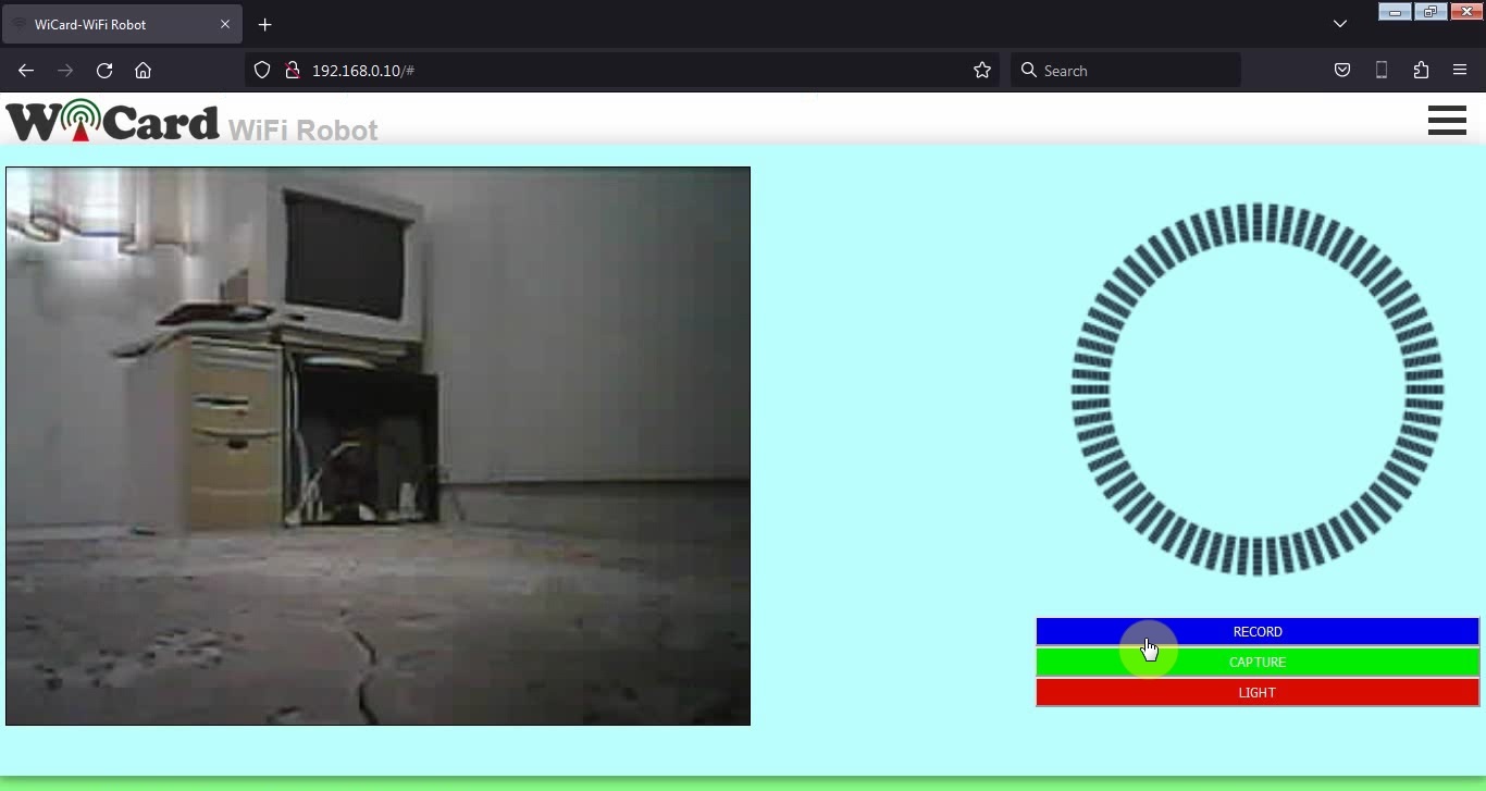
The video of WiFi controllable robot
This short video shows how it works:
In case of inserting memory card, by tap or click on the “RECORD” button, it starts recording video (the button’s name will change to “STOP”).
By tap or click on the “STOP” button, the recording will stop.
- The on-chip red LED of ESP32-Cam will turn on during video recording.
Capture button takes a photo and saves it in the memory card.
Light button turns the ESP32-Cam’s on chip power LED on or off.
Also there’s a camera vision (on-line stream) in the left side. By tap or click on it, the stream video will enlarge and the quality will increase.
The WiFi Controllable Robot project firmware is available in the following

Written by: M. Mahdi K. Kanan – Full stack electronics and programming engineer and the founder of WiCardTech