Over The Air Update
Introduction Of The Over The Air Update (OTA Update)
This article discusses about how to update a microcontroller’s program/chip firmware over the air (OTA Update).
With increasing the source code lines and the firmware/program size, probability of errors will increase. So the application of OTA update is usually in smart circuits with larger firmware size.
***<<< WiCardTech Online Project Store – Electronics, Software and App Projects For Engineers, Students and Hobbyists >>>***
Description
Program bugs always are a “possibility”, so after debugging, the produced devices need to have the new firmware and the best way is OTA update.
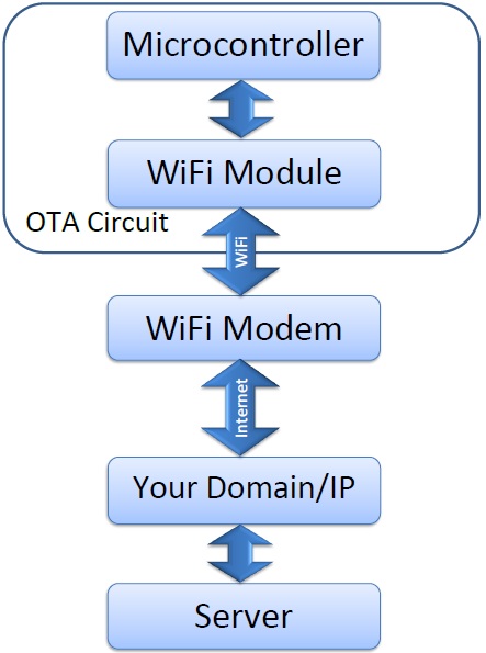
OTA Update Block Diagram:
The diagram shows that a microcontroller, with the help of a WiFi module, connects to a modem. Then it finds the server with its domain name or IP and receives the updates.
Firmware Update
Whether the update is wireless or wired, “Firmware update” or “Self programming” is writing new instruction codes in the program memory of a microcontroller and then executing the new instructions without connecting a programmer to the microcontroller (the firmware update can be a very simple example for “Artificial Intelligence Programming”, because your device has the ability of self debugging and upgrading in the software side).
One of the most common “Self programming” approaches is dividing the memory in 3 different blocks:
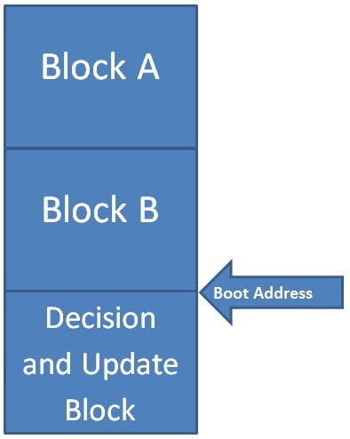
- Firmware backup A.
- Firmware backup B.
- Decision and Update Block (DUB).
First of all, save the current firmware block in the EEPROM memory. In addition, place the Decision and Update Block (DUB) at the boot section of your microcontroller. So when the device is powered on, it must first boot from DUB, then DUB decides to jump to the firmware backup block. In some microcontrollers there are instructions for self programming and both reading and writing flash program memory instructions are essential.
You need to have two compiled programs for the two firmware backup blocks. So there’s an “ORG” or “.org” assembly command which determines the current address in the program memory. For example, in the CodeVisionAVR, #asm(“.org 0x100”); means the program codes after this command must start after address 0x100, so you can use “.org 0x…” at the start of your source code before compiling the program, for each of the backup block A and B). When the current firmware is the block A, the new firmware must be written into the block B and vice versa. It is highly recommended to place and execute all of the write instructions in the DUB.
OTA Firmware Update and Circuit Setup
OTA Firmware Update is a firmware update which receives the new firmware via a wireless communication (usually WiFi) from a server (local or over the internet).
Here are the levels of an OTA update:
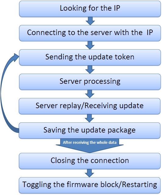
The Steps:
1- The device first looks for the IP of your server, if your server is connected to the internet and has a domain name, the device will get the server IP from the DNS servers.
2- The next step is connecting to the server with the IP. The device should open a connection to the server.
3- In this step the device will send the update token. Sometimes there’s not enough buffer memory for receiving the whole update date. So you can divide it to smaller packets and every token asks for a successive packet. For example, the update size is 24KB, but you have only 1KB free RAM in your device, so you need to download 24 separate 1KB packets.
4- According to the update token, the server will select and send the package (for example the device says I need the pack number 7 with this dynamic link: “mydomain.x/update?pack=7”).
5- Then the device will receive the data and stores the update data in its RAM.
6- After receiving the whole data of the package, the device will save it to its own program memory (Firmware Backup Block A or B, depending on the current using block). Before continue, the device must be sure that it has saved the data well. So the device reads the saved data and compares it with the data in the RAM. In addition if they were exactly the same, it will receive the next update pack (jumping to the step 3).
7- When the device downloaded and saved the whole of the update data, it will close the connection and prepare for a “Self-Restart”.
8- Before restarting, the device should save somewhere that it should start from the other firmware backup block for the next time (for example a boot byte in the eeprom memory), and then with using restart instructions, the device will restart (or jumping to the boot address, but data/function stack should be cleared first).
Server Setup
A server is a computer with an operating system and an internet connection which allows the other computers to have access on its processor/memory. If setting up a home-server, your internet modem does not allow outbound connections by default and it must be set in the “Port Forwarding” settings of the modem. Also the operating systems doesn’t allow this access by default and it needs to making some changes in the firewall setting of the OS. The usual port of the websites is 80 (HTTP port) and 443 (HTTPS). Every computer with every OS (Linux, windows or MAC) can work as a web server, but some softwares should be installed first to determine where the incoming connections from the port (80 or etc.) have to go. For example one of the simplest ways is using Wamp Server (Windows), or AAMPS (Windows, Linux, or MacOS).
Wamp Server is a virtual server which supports PHP language, MySQL, Apache and everything that a real web server needs to have. Then you can access to your web server with your IP and you can register a domain name for your IP (if your IP is static).
You have to put some PHP files and program to handle every incoming data/token from your device to OTA update (or etc.).
HTTP Protocol
Your device must send the data through a protocol. One of the simplest protocols is HTTP. For example to accessing to a “dynamic link” like “http://mydomain.x/update?pack=7”, you need to send a token like this:
GET /update?pack=7 HTTP/1.1
Host:mydomain.x

(+an empty line)
The host determines which domain you are attempting to connect to (because sometimes there are more than 100 different domains on a server). The “GET” method is one of the shortest and simplest methods (but not as safe).
But why we called that link a “dynamic link”? Because with using a link like that, the data will lead to a specific php file (for example “index.php” in the “update” folder) and in that file “$_GET[‘pack’]” is a variable with “7” as its value, so there is no need to be worry about which update pack is needed to send.
So the server response can be something like this:
HTTP/1.0 200 OK
X-Powered-By: PHP/5.5.38
Set-Cookie: PHPSESSID=a1325f0b410236d3b2271a39faa510; path=/
Expires: Thu, 19 Nov 1981 08:52:00 GMT
Cache-Control: max-age=0, private, no-cache, no-store, must-revalidate
Pragma: no-cache
Content-Type: text/html; charset=utf-8
Date: Thu, 21 Sep 2017 05:52:09 GMT
Accept-Ranges: bytes
Server: LiteSpeed
Connection: close

(+an empty line)
Hello World[PHP output/Html Data/What you see in the web browser, for example: print "Hello World!";]
Usually the only important part is the output string/data (Hello World!).
ESP8266
ESP8266 is a suitable chip/module for OTA update, so we use it as an OTA update example. If you’re using it as your WiFi module and you want to update your microcontroller via this module, the “AT Command Firmware” is the best way (usually it is already uploaded on the module’s flash).
If you want to use this as your main processor/microcontroller, you can use the provided “RTOS SDK APIs”.
-
AT Command
The following AT Commands are useful for the microcontroller to OTA update via an ESP module (the commands receives via UART port of the ESP module):
AT+CIPSTART:
Connecting to the domain/IP.
Example: AT+CIPSTART=”TCP”, “www.mydomain.x”, 80
AT+CIPSEND:
Sending the data (update token).
Example: AT+CIPSEND=50
[The module sends “>” and then is ready to receives 50 bytes of the data (update token) to sending to the server]
Example Token: GET /update?pack=7 HTTP/1.1
Host:mydomain.x
The server response will start with “+IPD”.
AT+CIPCLOSE:
Closes the connection.
-
RTOS SDK API
The ESP8266 has a well constant DUB which already has been uploaded by the factory into the chip and they have already divided the flash memory for the firmware backups for the OTA firmware update (FOTA). Here are some useful functions from the ESP8266 RTOS SDK APIs reference:
spi_flash_read:
Reading the data from the flash memory.
spi_flash_erase:
Erasing the data from the flash memory (4KB blocks).
spi_flash_write:
Writing the data into the flash memory (4KB blocks).
espconn_gethostbyname:
Looking for the server IP with its domain name.
espconn_connect:
Connect to the server via the server IP (Opens a connection).
espconn_send:
Sending the data through the connection.
espconn_regist_recvcb:
Registering the receive callback function for the connection.
espconn_disconnect:
Disconnects from the server (Close the connection).
Conclusion
In this article, we talked how theoretically we can update a circuit’s firmware without using a programmer and how we can receive the update data over the air and internet, via a WiFi connection and from a server.
OTA update will fix the bugs without touching the device and it’s useful for the products which have a wide range of features. With the firmware update, the system designer and producer can produce the product in a high quantity without being worry about the potentially bugs in the firmware.
WiCard WiFi module uses OTA update to upgrading its own firmware.

Written by: M. Mahdi K. Kanan – Full stack electronics and programming engineer and the founder of WiCardTech
One Response
Keep on writing, great job!
Comments are closed.