Nokia LCD (6125) setup and programming
Here’s a simple circuit and code which is compatible with PCF8833 driver for old Nokia LCD (tiny LCDs) such as 1208, 1600, 2126, 2310, 6100, 6125, N71.
The circuit and code in this project is compatible with PCF8833 STN RGB – 132*132*3 LCD driver.
This LCD driver has been used for some Nokia tiny LCDs such as 1208, 1209, 1600, 2126, 2310, 6100 and 6125, 6136, N71 back LCD.
The LCD that I have worked on it is a 98*70 pixel LCD which I have removed from a wrecked Nokia 6125.
This LCD needs a board-to-board connector which I removed from Nokia’s PCB. The transaction line for my LCD is a 9-bit SPI which has no transmit line and only receives the data or command from the host.
The host (controller, driver or etc.) that I have used is an ATMega8A microcontroller.
ATMega8A has a 8-bit SPI feature, not a 9-bit, so I have used the I/Os directly instead of the internal SPI module.
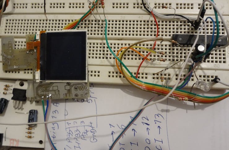
The Nokia LCD Circuit
Here’s my circuit on a breadboard:
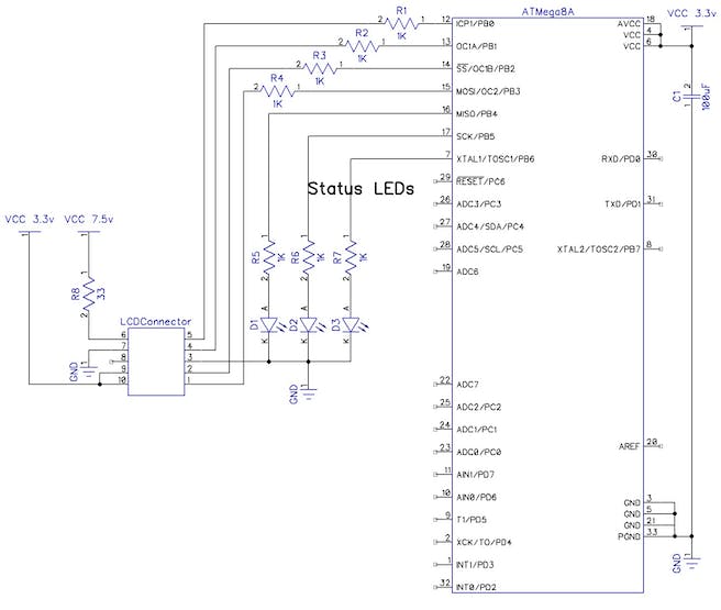
The Schematic
Here’s the pinout of my LCD:
1. CLK
2. Data
3. GND
4. CS#
5. RESET#
6. Back light LED+, 7.5V
7. Back light LED-, GND
8. NC
9. VddAN, 2.8V… 3.3V
10. VddIO, 1.8V… 3.3V
Here’s the schematic:
Transaction Protocol
When Reset# pin is low, that means LCD is in reset state and doesn’t accept the command and data.
When CS# is low, the LCD will accept the commands/data.
Here’s command protocol in 9-bit SPI:
        __   __   __   __   __   __   __   __   __
CLK ___|C1|_|C2|_|C3|_|C4|_|C5|_|C6|_|C7|_|C8|_|C9|____...

Data_______<b7 ><b6 ><b5 ><b4 ><b3 ><b2 ><b1 ><b0 >    ...
    _                                               __
CS#  |______________________________________________|  ...
Here’s data protocol in 9-bit SPI:
        __   __   __   __   __   __   __   __   __
CLK ___|C1|_|C2|_|C3|_|C4|_|C5|_|C6|_|C7|_|C8|_|C9|____...
      ___
Data_|   |_<b7 ><b6 ><b5 ><b4 ><b3 ><b2 ><b1 ><b0 >    ...
    _                                               __
CS#  |______________________________________________|  ...
Nokia LCD Initialization
For the initialization I sent these commands and data first:
command: 0x11
command: 0x20
command: 0x3A
Data: 0x05
command: 0x36
Data: 0xC8
command: 0x25
Data: 0x30
command: 0x29
command: 0x2A
Data: 0x00
Data: 97 (Number of pixel column – 1)
command: 0x2B;
Data: 0x00
Data: 69 (Number of pixel lines or rows – 1)
Source Code Example
Here is the source code example for changing the background color of the lcd:
/*******************************************************
This program was created by the
CodeWizardAVR V3.12 Advanced

Chip type               : ATmega8A
AVR Core Clock frequency: 8.000000 MHz (Internal)
*******************************************************/

#include <mega8.h>

register unsigned char		ucI,rucJ,rucK,i,j;

void vCMD();
void vData();
void vSend();
void vClk();
void vDelay();

// 1mS Timer 0 overflow interrupt service routine
interrupt [TIM0_OVF] void timer0_ovf_isr(void)
{
    rucJ++;
    TCNT0 = 125;//about 1mS
    TIFR = 0x01;
}

void main(void)
{
  //Microcontroller init
  PORTB = 0x0A;
  DDRB = 0x3F;

	OSCCAL = 0x99;

  //Low level external interrupts - sleep enable
  MCUCR = 0x8A;

	//Timer 0
  TCNT0 = 0;
  TCCR0 = 0x03;
  TIFR = 0x01;
  TIMSK = 0x01;

	#asm("sei");

  //PORTB.PORTB0		//RST#
  //PORTB.PORTB1		//CS#
  //PORTB.PORTB2		//SI
  //PORTB.PORTB3		//SCK

  PORTB.PORTB0 = 0;		//RST#
  rucK = 250;
  //1 second delay
	vDelay();
	vDelay();
	vDelay();
	vDelay();

  PORTB.PORTB4 = 1; //Status LED 1 On
	vDelay();

  //LCD Reset
  rucK = 1;
  PORTB.PORTB0 = 1;		//RST#
	vDelay();
  PORTB.PORTB0 = 0;		//RST#
	vDelay();
  PORTB.PORTB0 = 1;		//RST#

  //LCD Init
  ucI = 0x11;
  vCMD();

  ucI = 0x20;
  vCMD();

  ucI = 0x3A;
  vCMD();
  ucI = 0x05;
  vData();

  ucI = 0x36;
  vCMD();
  ucI = 0xC8;
  vData();

  ucI = 0x25;
  vCMD();
  ucI = 0x30;
  vData();

  ucI = 0x29;
  vCMD();

  PORTB.PORTB5 = 1;
  rucK = 250;
  vDelay();

  //98*70
  ucI = 0x2A;
  vCMD();
  ucI = 0;
  vData();
  ucI = 97;
  vData();

  ucI = 0x2B;
  vCMD();
  ucI = 0;
  vData();
  ucI = 69;
  vData();

  //0xFFFF White
  //0x0000 Black

  while(1)
  {
    ucI = 0x2c; // Screen data command
    vCMD();

    //First line
    //Border white
  	for(j = 0; j < 98; j++)
    {
    	//1st byte: BBBBB GGG
      //2nd byte: GGG RRRRR
	    ucI = 0xFF;
	    vData();
	    ucI = 0xFF;
	    vData();
    }

    //Second line
    ucI = 0xFF;
    vData();
    ucI = 0xFF;
    vData();

    //Border Black
  	for(j = 0; j < 96; j++)
    {
    	//1st byte: BBBBB GGG
      //2nd byte: GGG RRRRR
	    ucI = 0x00;
	    vData();
	    ucI = 0x00;
	    vData();
    }

    ucI = 0xFF;
    vData();
    ucI = 0xFF;
    vData();

    //Blue screen
    for(i = 0; i < 66; i++)
    {
      //Border
	    ucI = 0xFF;
	    vData();
	    ucI = 0xFF;
	    vData();
	    ucI = 0x00;
	    vData();
	    ucI = 0x00;
	    vData();

    	for(j = 0; j < 94; j++)
      {
      	//1st byte: BBBBB GGG
        //2nd byte: GGG RRRRR
		    ucI = 0xF8;
		    vData();
		    ucI = 0x00;
		    vData();
      }
	    ucI = 0x00;
	    vData();
	    ucI = 0x00;
	    vData();
	    ucI = 0xFF;
	    vData();
	    ucI = 0xFF;
	    vData();
    }

    //Border
    ucI = 0xFF;
    vData();
    ucI = 0xFF;
    vData();

  	for(j = 0; j < 96; j++)
    {
    	//1st byte: BBBBB GGG
      //2nd byte: GGG RRRRR
	    ucI = 0x00;
	    vData();
	    ucI = 0x00;
	    vData();
    }
    ucI = 0xFF;
    vData();
    ucI = 0xFF;
    vData();

    //White border
  	for(j = 0; j < 98; j++)
    {
    	//1st byte: BBBBB GGG
      //2nd byte: GGG RRRRR
	    ucI = 0xFF;
	    vData();
	    ucI = 0xFF;
	    vData();
    }

    vDelay(); //250 mS Delay

    //Green screen
    ucI = 0x2c; // Screen data command
    vCMD();

    for(i = 0; i < 70; i++)
    {
    	for(j = 0; j < 98; j++)
      {
		    ucI = 0x07;
		    vData();
		    ucI = 0xE0;
		    vData();
      }
    }

    vDelay(); // 250mS Delay

    //Red Screen
    ucI = 0x2c; // Screen data command
    vCMD();

    for(i = 0; i < 70; i++)
    {
    	for(j = 0; j < 98; j++)
      {
		    ucI = 0x00;
		    vData();
		    ucI = 0x1F;
		    vData();
      }
    }

    vDelay(); //250mS
  };
}

void vCMD()
{
  PORTB.PORTB1 = 0;		//CS#

  #asm("NOP");
  #asm("NOP");
  #asm("NOP");
  #asm("NOP");

	PORTB.PORTB2 = 0;		//SI#

  #asm("NOP");
  #asm("NOP");
  #asm("NOP");
  #asm("NOP");

  vSend();
}

void vData()
{
  PORTB.PORTB1 = 0;		//CS#

  #asm("NOP");
  #asm("NOP");
  #asm("NOP");
  #asm("NOP");

	PORTB.PORTB2 = 1;		//SI#

  #asm("NOP");
  #asm("NOP");
  #asm("NOP");
  #asm("NOP");

  vSend();
}

void vSend()
{
  vClk();

  if(ucI & 0x80)
  	PORTB.PORTB2 = 1;		//SI#
  else
  	PORTB.PORTB2 = 0;		//SI#

  vClk();

  if(ucI & 0x40)
  	PORTB.PORTB2 = 1;		//SI#
  else
  	PORTB.PORTB2 = 0;		//SI#

  vClk();

  if(ucI & 0x20)
  	PORTB.PORTB2 = 1;		//SI#
  else
  	PORTB.PORTB2 = 0;		//SI#

  vClk();

  if(ucI & 0x10)
  	PORTB.PORTB2 = 1;		//SI#
  else
  	PORTB.PORTB2 = 0;		//SI#

  vClk();

  if(ucI & 0x08)
  	PORTB.PORTB2 = 1;		//SI#
  else
  	PORTB.PORTB2 = 0;		//SI#

  vClk();

  if(ucI & 0x04)
  	PORTB.PORTB2 = 1;		//SI#
  else
  	PORTB.PORTB2 = 0;		//SI#

  vClk();

  if(ucI & 0x02)
  	PORTB.PORTB2 = 1;		//SI#
  else
  	PORTB.PORTB2 = 0;		//SI#

  vClk();

  if(ucI & 0x01)
  	PORTB.PORTB2 = 1;		//SI#
  else
  	PORTB.PORTB2 = 0;		//SI#

  vClk();

  PORTB.PORTB1 = 1;		//CS#
}

void vClk()
{
  PORTB.PORTB3 = 0;		//SCK#

  #asm("NOP");
  #asm("NOP");
  #asm("NOP");
  #asm("NOP");
  PORTB.PORTB3 = 1;		//SCK#

  #asm("NOP");
  #asm("NOP");
  #asm("NOP");
  #asm("NOP");
}

void vDelay()
{
	rucJ = 0;

  while(rucJ < rucK) //100 mS delay
  {
  	#asm("sleep");
  };
}
Written by: M. Mahdi K. Kanan – Full stack electronics and programming engineer and the founder of WiCardTech