WiFi Spy Microphone With ESP8266 and NodeMCU
I have updated WiFi Spy Microphone project and now the newer revision of this project is available in the following links:
ESP8266 WiFi Spy Microphone Arduino Source Code (ESP12, NodeMcu…) – Rev 2.0
The free source code of the older revision:
ESP8266 WiFi Microphone (ESP12, NodeMcu…) – Rev 1.2
When ever I updated this project, I told myself “Wow man, this one is really different”, but this time really really is different.
I’ve increased the quality and the bit-rate.
Anyway, If you already have bought this project, now you can download this revision for free and if you forgot your order code, don’t worry, just email me with the email address which you have bought the project.
A little bit about WiFi SPY Microphone project
The “Ai Thinker ESP12” module has an ACD pin which works in range of 0V to 1V and NodeMCU’s ADC pin works in range of 0V to 3.3V with 10 bits resolution (0-1023). The pin in ESP8266 modules is between RST and EN and in NodeMCU is A0. In the “WiFi Microphone” project, we have used this channel as the audio signal input.
The module reads audio signal from ADC pin, then decode it to audio data and transmits it to the web browser. Web browser receives the data and stars recording it to a WAV file. Also the user can play the recorded audio live-ly.
This project contains two folders ESP8266WiFiMicrophone (the WiFi Microphone source code) and PHP Script (For server use option).
The source code contains 4 files:
1- ESP8266WiFiMicrophone.ino – the main program
2- AC.ino (autoconnect handler)
3- AC.h (configuration headerfile)
4- MicPage.ino (Microphone’s page and decoder)
First open one of the files with Arduino program, then set the settings as the following image (Board, CPU Frequency and Flash Frequency):
• The CPU frequency must be set on 160MHz.
• The “Board” must be set on the “Generic ESP8266 Module” (or similar) before doing anything.
Then put the ESP8266 module on the “download mode” and upload the program.
The Circuit
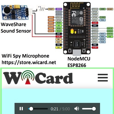
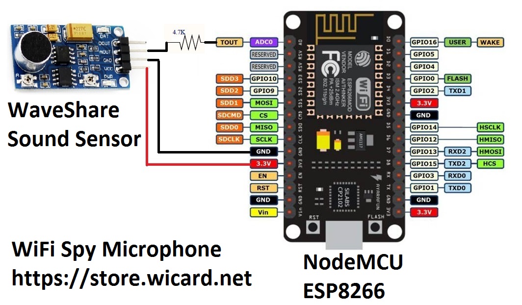
It’s suggested to use a standard 3.3V microphone module like “WaveShare Sound Sensor”.
Before using the WiFi microphone, build one of the following circuits.
Here’s a simple circuit with WaveShare Sound Sensor and NodeMCU:
And also there is a suggested circuit with a simple capacitive microphone, LM386 and NodeMCU or ESP8266MOD (ESP12) in the manual pdf file.
Now plug the power and turn on the circuit and the module in “normal mode”.
Then in case you are using ESP12, the blue LED on the board would be turned on for 1 second then turns off. Then you’ll be able to see the module’s hot spot ssid via the WiFi networks in your PC or smart phone.
The default SSID is WiCardMp and the default password is 12345678. Connect and go to 192.168.4.1 with a PC or smart phone web browser.
Here’s the web UI:

Right after loading the page, the module starts recording automatically. By clicking on the play button, the recorded sound will play.
In the right top of the page, there is a menu button, here are the menu items:

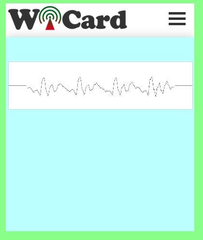
“Scope” will lead to audio signal oscilloscope page. In this page you can check the audio signal and set the best output by turning the sound sensor potentiometer.
“Settings” will lead you to the WiFi and device configuration page:
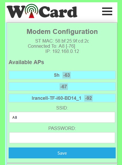
This page shows the WiFi connection status, available access points and etc. Also in this page you can configure the hotspot connections and recording settings.
In the “Modem Configuration” section, you’re able to view/edit the SSID and password of WiFi modem/router and then click on “Save” after inserting. The module would connect to the modem after about 30 seconds in case of validity of ssid and password.
• This page is also available via the DHCP IP of the module. The given IP address for the above picture is 192.168.0.12.
In the “Device Hot Spot Configuration” section, you can set the module hotspot’s SSID and password. Also you can set a password for the internal page with Secure Link section. (Example: the secure link is ABCD and the root page would be at 192.168.4.1/ABCD/ address)
The “Hidden HotSpot” button will set the module’s hot spot as hidden hotspot and the “Disable HotSpot when is connected to the modem” would disable the module’s hotspot, when is connected to the modem.
The Stream Configuration
With “Audio Stream Bitrate” the quality of the audio stream can be set in 80, 90 or 100Kbps.
• The signal strength must be higher for higher quality.
The “Audio Stream Packet Length” sets the stream time in 5, 10, 30 or 60 minutes.
“Audio Stream Software Amplitude” increases the sound volume of the output data.
• In case of using a strong microphone module or loud input audio, there’s no need to the software amplitude.
The project is available in the following:
Revision History:
1.3
Schematic improvement
The Web UI has been changed
increasing the quality of the recorded sound
Increasing the bitrate up to 100kbps
reducing the noises
Bugs fixed
1.2
Schematic improvement
Secure link debug
ADC input improvement
Output file improvement
Selectable stream quality
Adjustable stream time
Adjustable software amplitude
1.1
-10:28 frame (increased)
-Audio stream recorder and player
-8KHz sample rate (increased)
-10 bits resolution (increased)
-Calibration page
-The stability and quality of audio stream increased
-Suggested test circuit updated
-Bugs fixed
1.0
-3300 miliseconds frames
-LOUD button
-7.5KHz sample rate
-8 bits resolution
-Internal pages secure link
-Show MAC and IP in config page
-Set module hotspot and modem’s ssid and password
-Automatically connection to the modem
-Config page
-Hidden hotspot button
-Disable hotspot button
More projects in our blog.

Written by: M. Mahdi K. Kanan – Full stack electronics and programming engineer and the founder of WiCardTech