SpyCam Project (Video and Audio Recorder) With Ai Thinker ESP32-Cam
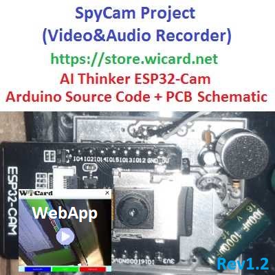
The SpyCam project uses the “AI Thinker ESP32-CAM” module which has a 2MP Camera, 10 I/O pins, an on-chip LED and one MicroSD slot to store the images and videos. With its tiny sized camera and 240MHz CPU is able to provide a fair quality images and video frames.
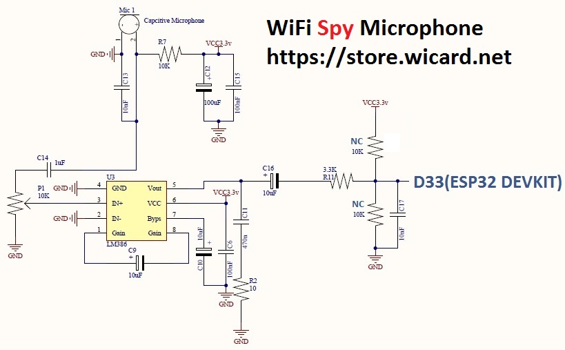
You can either use a “WaveShare Sound Sensor” (or similar) or the suggested circuit as the audio input.
This project is available in the following link:
SpyCam Project (Video&Audio Recorder) Source Code, PCB and Schematic Plans (ESP32-Cam) – Rev 2.0
Also there’s another project which is only video recorder without the handler circuit:
Arduino ESP32-CAM CCTV, WiFi IP Camera Source Code – Rev 2.0
And the free binary of the firmware of above project (older revision):
Firmware Binary File of Ai Thinker ESP32-CAM CCTV, WiFi IP Camera – Rev 1.1
Preparing the module for SpyCam
The ADC input (for the audio circuit) is GPIO 33 which is originally connected to the red on-board LED.
This project contains three folders ESP32CamProgram (the Arduino source code), PHP Script (For updating the IP option) and PCB-SCH-BOM.
First of all you need the GPIO 33, so remove the LED and connect a short wire to the LED’s “Cathode” pad.
- You can remove the LED with a standard “Iron” or break the LED, but be careful and do not hurt the LED’s pad.
- It’s recommended do NOT use “Hot Air”, it may hurt the module parts.
- Fix the wire with a stick.
- In the above picture, I have stuck a heat sink to the module’s regulator. It’s not necessary but recommended.
The SpyCam’s Circuit
You can connect the WaveShare sound sensor analog output to the wire with a 3.3K resistor or use the suggested circuit. Also there’s a PCB file in the PCB-SCH-BOM folder.
- The ESP32-Cam module must be connected to the bottom layer.
The SpyCam’s WebApp
After uploading the program, you can insert a micro SD memory card (FAT or FAT32 format) and turn on the module in normal mode (Leave GPIO0 un-connectd).
Then the LED which is connected to the GPIO 0, would be turned on for 1 second then turns off. Then you’ll be able to see the module’s hot spot ssid via the WiFi networks in your PC or smart phone.
The default SSID is WiCardCam and the default password is 12345678. Connect and go to the root page address (192.168.4.1) with a web browser, then you’ll be able to see the WebApp and the on-line video stream.
Currently the online stream is without audio, but this feature will be added in the future.
By tap on the video image, the image will scale to full with and original size.
There are two buttons under the stream image, with “CAPTURE”, the module will take and save a shot and with tap or click on the “LIGHT” button, the on-chip flash light will turn on and off.
By tap or click on the “menu button” (top-right), the menu items will be appeared:
The first item will lead you to the current (cc video/online video stream) page.
The second item is the scope page which has an oscilloscope on the audio ADC input and shows the input audio signal:
Memory Page
The third item will lead you to the memory files and video player.
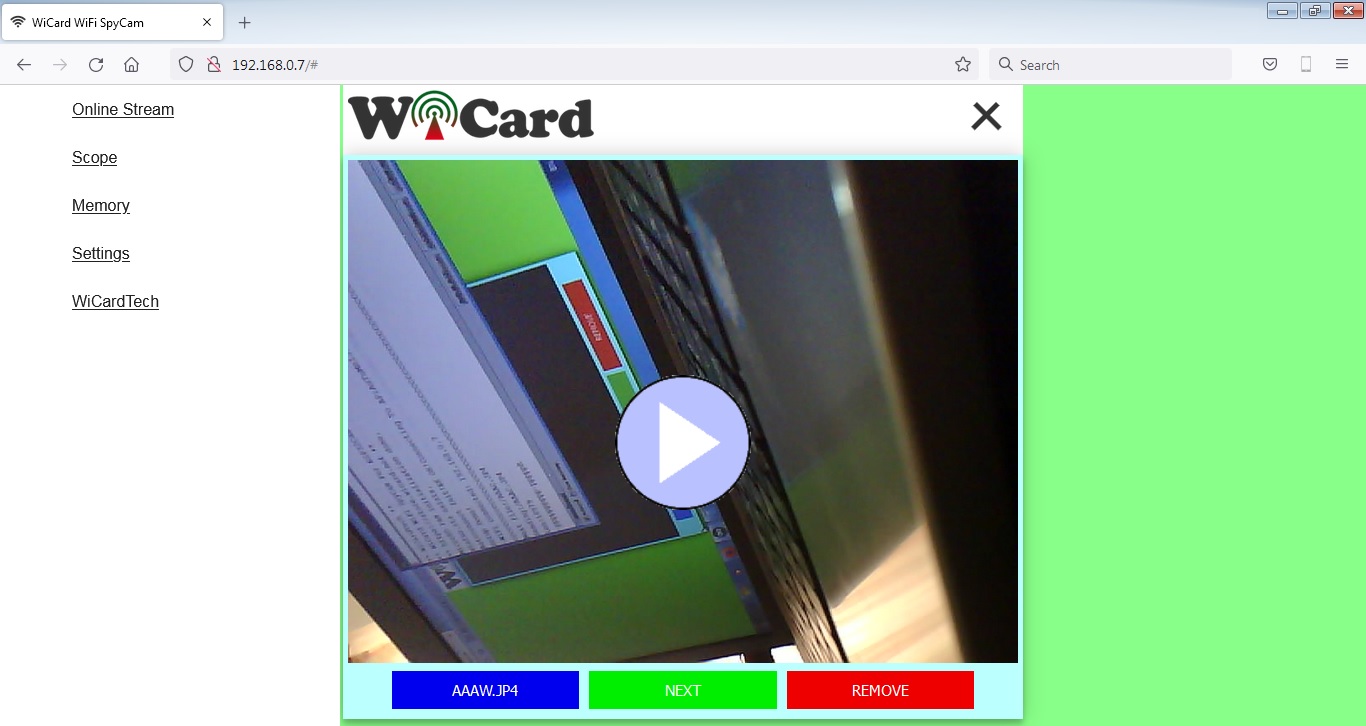
The SpyCam saves two type file in its microSD memory, .JPG file for the image shots and .JP4 for the recorded video and audio. The left button under the image shows the file name and has the direct link of file (you can right click on it and copy the link), the middle button shows the next file, and the right button, removes the file.
By click on the play button (middle of the JP4 file image), the video will be downloaded and played along with the audio and you can pause the video by tap or click on the image.
Currently you can only play the .JP4 files in this page.
- Downloading the videos may take a while, it depends on the video data length and the WiFi signal strength.
SpyCam WiFi Configuration
The fourth item in the menu, will lead you to the WiFi configuration and system settings page.
This page shows the WiFi connection status, available access points and etc. Also in this page you can configure the hotspot connections and recording settings.
In the “Modem Configuration” section, you’re able to view/edit the SSID and password of WiFi modem/router and then click on “Save” after inserting. The module would connect to the modem after about 30 seconds in case of validity of ssid and password.
- The SpyCam WebApp is also available via the DHCP IP of the module. The given IP address for the above picture is 192.168.0.12.
In the “Device Hot Spot Configuration” section, you can set the module hotspot’s SSID and password. Also you can set a password for the internal page with Secure Link section. (Example: the secure link is ABCD and the root page would be at 192.168.4.1/ABCD/ address)
The “Hidden HotSpot” button will set the module’s hot spot as hidden hotspot and the “Disable HotSpot when is connected to the modem” would disable the module’s hotspot, when is connected to the modem.
The SpyCam Camera Configuration Section:
With the first option menu you can choose the video quality between Low (320*240), Medium (640*480) and High (800*600).
By the second option menu you can set the recording time to 10, 30 or 60 seconds.
The PIR switch actives the PIR input pin (GPIO 3-active high). You can connect the PIR module (Body temperature detector) output (or other kinds of motion detector modules) to this pin with a load and a pull down resistor. The resistors’ value depend on the PIR module output voltage.
- The input voltage to the GPIO 3 pin should not exceed 3.3V, otherwise it my hurt the module.
The “Motion Detection” switch turns on the internal software based motion detector. In this case, the module captures a shot every second and compare’s the images and decides for recording a video or not.
With “Motion Sensivity” option menu, you can choose, low, medium or high option.
The “Flash Light” switch turns the Flash light on or keeps it off during video recording.
The projects are available in the following:

Written by: M. Mahdi K. Kanan – Full stack electronics and programming engineer and the founder of WiCardTech