ESP8266 Microphone (WiFi) With Arduino – Updated
The “Ai Thinker ESP12” module (ESP8266MOD) has an ACD pin (works in range of 0V to 3.3V) with 10 bits resolution (0-1023). The pin is between RST and EN. In the WiFi ESP8266 Microphone project, we have used this channel as the audio signal input.
The ESP8266 Microphone and ESP32 Microphone Audio Stream Page
This page is in the root address (192.168.4.1 or the router’s given IP).
The module reads audio signal from ADC pin, then decodes it to audio data and transmits it to the web browser. Web browser receives the data and stars recording it to a WAV file. Also the user can play the recorded audio and listen to it lively at the same time.
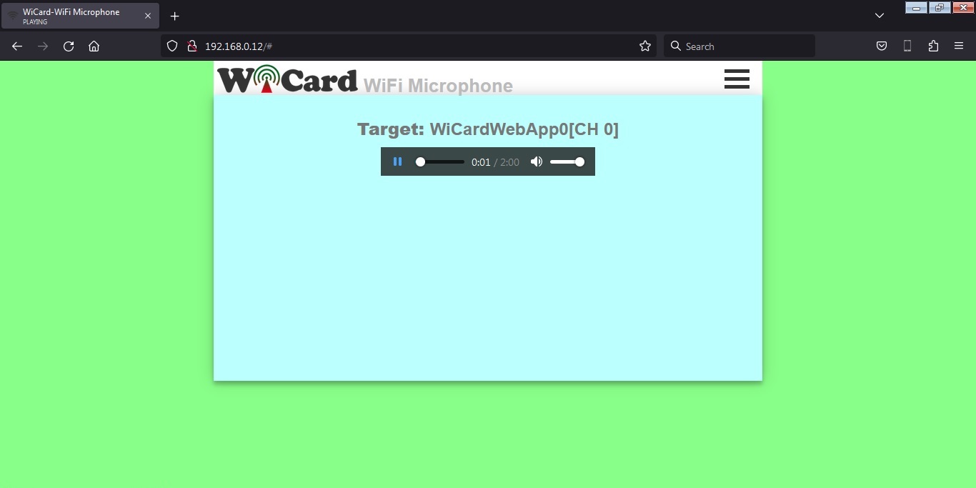
The preset time is 10 minutes. After this time spent, you can save the file by right click on the player and click on “save as”, or you can refresh the page and record again.
- If you close the web page, recording will be aborted.
Microphone Calibration
There is a calibration page in “192.168.4.1/cal” which shows the audio signal. When there’s no noise and voice, the signal must be a straight horizontal line at the center of scope.
Also you can see the input audio signal shape in this page:
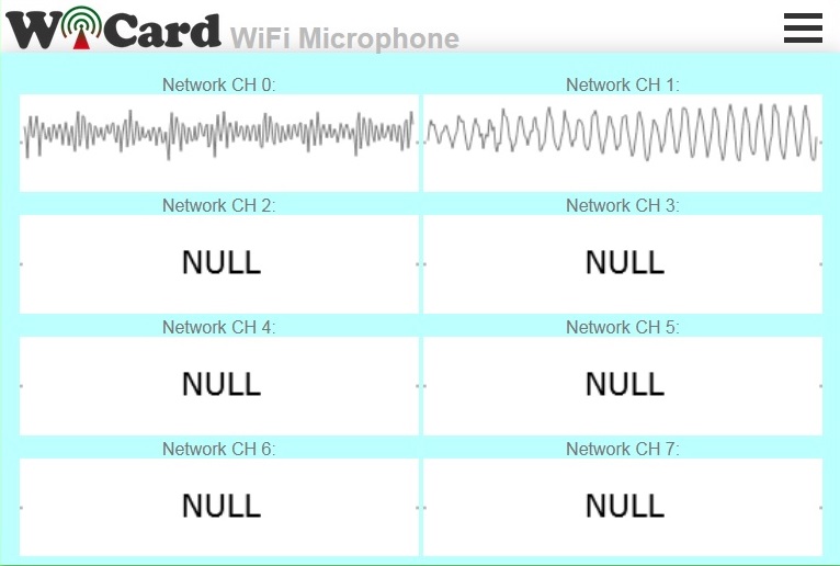
The audio signal uses 8000Hz sample rate with 10 bits resolution which gives a fair quality sound.
- The WiFi signal strength takes effect on the module capability and the audio streams.
- The average voltage (silent voltage) is 1.65V (half of the 3.3V power source).
The Circuit
Better to use a standard 3.3V microphone module. But here’s a suggested minimum circuit with a simple capacitive microphone, ESP8266 connections and voltage regulation to testing the program:
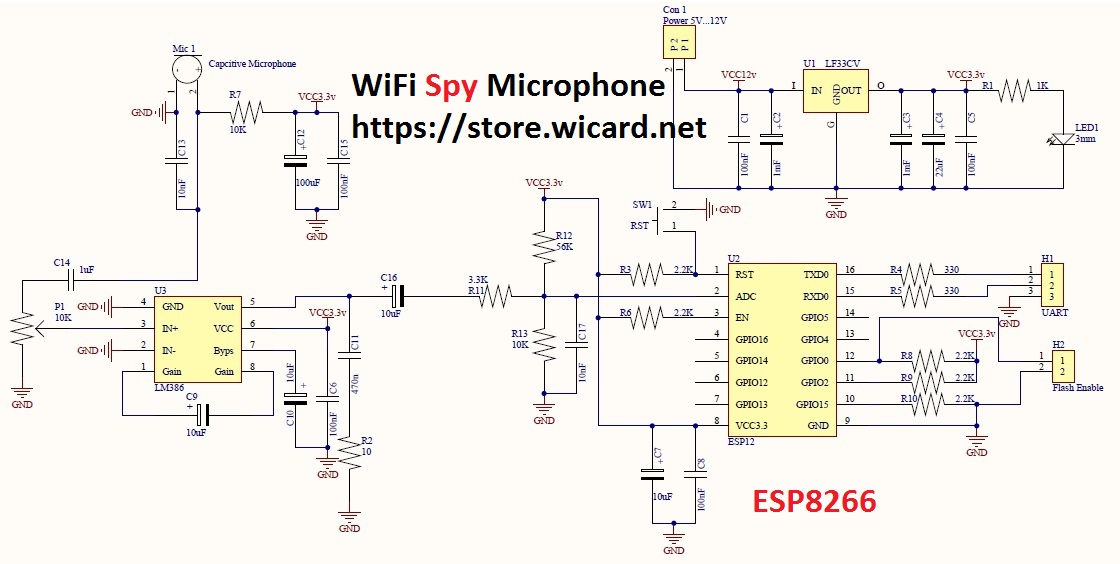
In the above schematic, LED1 shows the power is on, SW1 is the ESP8266 module reset button, H1 is the module’s UART connector (for flashing/programming) and H2 pin header needs a jumper to put the ESP12 module in the flash programming mode.
The microphone block has a potentiometer (P1) to calibrating the input audio signal.
- Better to use a 5-12V power source with 2A output drain capability.
- The module must only receive 3.3v (from the LF33 regulator). Higher voltage will hurt the module.
The project and its free DEMO revision is available in the following (If you already have bought this project, just insert your order code in the orders section and download the updated revision.):
In this updated revision, we have made the following changes:
Revision 1.1
- 10:28 frame (increased)
- Audio stream recorder and player
- 8KHz sample rate (increased)
- 10 bits resolution (increased)
- Calibration page
- The stability and quality of audio stream increased
- Suggested test circuit updated
- Bugs fixed
Revision 1.0 (previous revision)
- 3300 miliseconds frames
- LOUD button
- 7.5KHz sample rate
- 8 bits resolution
- Internal pages secure link
- Show MAC and IP in config page
- Set module hotspot and modem’s ssid and password
- Automatically connection to the modem
- Config page
- Hidden hotspot button
- Disable hotspot button
Tested with Arduino ESP8266 board 2.6.3 and Ai Thinker ESP8266MOD module.
If you have any questions, please use the comment form or refer to contact us.

Written by: M. Mahdi K. Kanan – Full stack electronics and programming engineer and the founder of WiCardTech